Figure 1. Representative Block Diagram
15 鈥?/div>
V
DC Mode or
400 Hz Input
RP 14
Protection
Circuit
Zero
Crossing
Detector
MT2
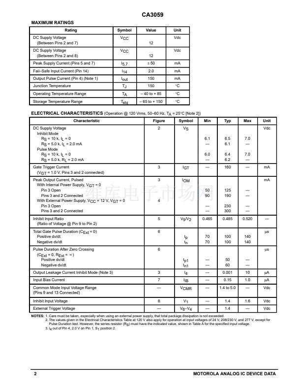
FUNCTIONAL BLOCK
DESCRIPTION
1.
Limiter鈥揚(yáng)ower Supply
鈥?Allows operation of
the CA3059 directly from an AC line. Suggested
dropping resistor (RS) values are given in the table
below.
2.
Differential On/Off Sensing Amplifier
鈥?Tests
for condition of external sensors or input command
signals. Proportional control capability or hysteresis
may be implemented using this block.
3.
Zero鈥揅rossing Detector
鈥?Synchronizes the
output pulses to the zero voltage point of the AC cycle.
This synchronization eliminates RFI when used with
resistive loads.
4.
Triac Drive
鈥?Supplies high鈥揷urrent pulses to
the external power controlling thyristor.
5.
Protection Circuit
鈥?A built鈥搃n circuit may be
actuated, if the sensor opens or shorts, to remove the
drive current from the external triac.
6.
Inhibit Capability
鈥?Thyristor firing may be
inhibited by the action of an internal diode gate at
Pin 1.
7.
High Power DC Comparator Operation
鈥?/div>
Operation in this mode is accomplished by connecting
Pin 7 to Pin 12 (thus overriding the action of the
zero鈥揷rossing detector). When Pin 13 is positive with
respect to Pin 9, current to the thyristor is continuous.
Triac
Drive
4
MT1
Gate
13
9
*
RX
10
11
+
On/Off
Sensing
Amp
鈥?/div>
VCC
8
Gnd
* NTC Sensor
7
1
Inhibit
6
External Trigger
AC Input Voltage
(50/60 Hz)
Vac
24
120
208/230
277
Input Series
Resistor (RS)
k鈩?/div>
2.0
10
20
25
Dissipation Rating
for RS
W
0.5
2.0
4.0
5.0
漏
Motorola, Inc. 1996
Rev 0
MOTOROLA ANALOG IC DEVICE DATA
1


 1
1
 2
2
 3
3
 4
4
 5
5
 6
6
