Type C1Q
C1QD0104
1206 size
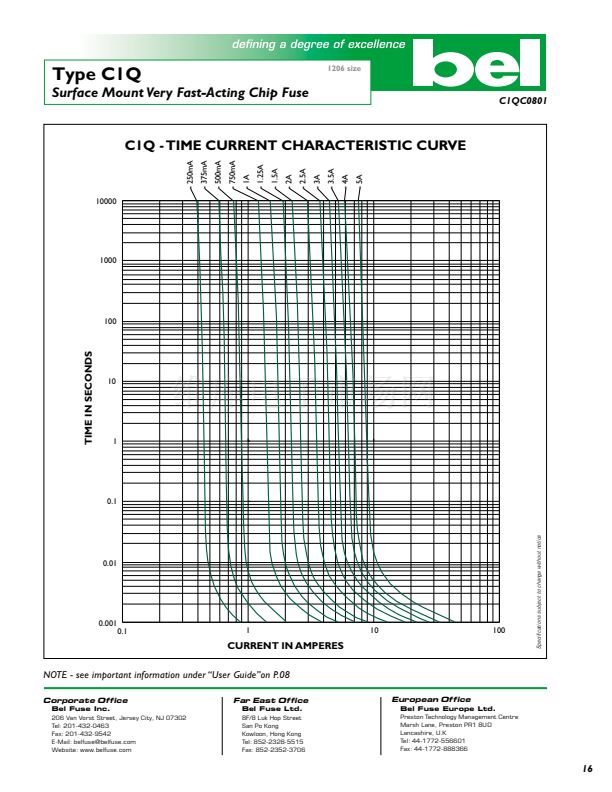
Surface Mount Very Fast-Acting Chip Fuse
Catalog
Number
Ampere
Rating
Typical
Cold
Resistance
(ohm)
Volt-drop
@100%
In
(Volt) max.
Melting I
2
T
@10
In
(A
2
Sec)
Maximum
Power
Dissipation
(W)
C1Q 250
C1Q 375
C1Q 500
C1Q 750
Testing current
100%
200%
300%
Blow Time
Minimum
4 hrs
N/A
N/A
Maximum
N/A
5 sec
0.2 sec
250mA
375mA
500mA
750mA
1A
1.25A
1.5A
2A
2.5A
3A
3.5A
4A
5A
0.88
0.47
0.32
0.175
0.119
0.087
0.070
0.049
0.038
0.032
0.028
0.025
0.021
0.31
0.26
0.23
0.19
0.17
0.16
0.15
0.14
0.14
0.14
0.14
0.14
0.15
0.0002
0.0004
0.001
0.002
0.004
0.007
0.010
0.020
0.034
0.052
0.076
0.10
0.17
0.10
0.12
0.14
0.18
0.21
0.24
0.28
0.35
0.43
0.52
0.62
0.71
0.96
Electrical Characteristics
(UL/CSA STD. 248-14)
C1Q 1
C1Q 1.25
C1Q 1.5
C1Q 2
C1Q 2.5
C1Q 3
C1Q 3.5
C1Q 4
C1Q 5
Approvals
Safety Agency Approvals
V脽c
Amp range / Volt @ I.R. ability
250mA-5A / 125V AC@ 100A
and 63V DC@ 50A
250mA-3A / 125V AC@ 100A
and 63V DC@ 50A
V
Listed File No. E20624
脽
Certified File No. LR39772
Consult manufacturer for other ratings
Physical Specification
Materials
Ceramic Substrate / Printed Element
Environmental Specification
Soldering Techniques & Compatibility
Reflow: Industrial standard, 260擄C peak
Wave Solder: 260擄C, 10 sec max. (MIL-STD-202, Method 210)
Shock
MIL-STD-202, Method 213, Test Condition I
(100 G鈥檚 peak for 6 milliseconds)
Vibration
MIL-STD-202, Method 201 (10-55 Hz, 0.06 inch,
total excursion)
Salt Spray
MIL-STD-202, Method 101, Test Condition B (48 hrs)
Insulation Resistance
MIL-STD-202, Method 302, Test Condition A
(After Opening) 10,000 ohms minimum
Solderability
MIL-STD-202, Method 208
Resistance to Solder Heat
MIL-STD-202, Method 210, Test Condition F
(260擄C, 20 sec)
Thermal Shock
MIL-STD-202, Method 107, Test Condition B
(-65擄C to +125擄C)
Operating Temperature
-55擄C to +125擄C
Marking
On fuse:
None
Label on reel:
鈥渂el鈥? 鈥淐1Q鈥? 鈥淐urrent Rating鈥? 鈥?25V; Interrupting Ratings鈥?&
鈥淰脽c鈥?/div>
Packaging
5,000 fuses in 7 inches dia. reel, 8 mm wide tape, 4mm pitch,
per EIA-481 (equivalent IEC-286 part 3)
Mechanical Dimensions
1.52
_
( 0 . 0 6 0m m +0 . 1 0 m m
_
" +0 . 0 0
4")
0 .5 8 m +
m
( 0 .0 2 3
-
0 .0 8 m m
+
"
-
0 .0 0
3")
0
3.07
( 0 . 1 2 1m m
-
+0 . 1 3 m
"
-
+0 . 0 0 m
5")
+
( 0 .0 1 4 "
m
_
0 .1 5 m m
+
_
0 .0 0 6
")
.3 6 m
C1Q
1.78mm
(0.07")
1.52mm
(0.06
"
)
2.03mm
(0.08
")
1.14mm
(0.045
")
PAD LAYOUT RECOMMENDED
FOR INFRARED SOLDER
1.52mm
(0.06")
1.52mm
(0.06
")
PAD LAYOUT RECOMMENDED
FOR WAVE SOLDER
ORDERING INFORMATION SEE PAGES 67 & 68
Bel Fuse Inc.
206 Van Vorst Street, Jersey City, NJ 07302 鈥?Tel: 201-432-0463 鈥?Fax: 201-432-9542 鈥?E-Mail: belfuse@belfuse.com
Website: www.belfuse.com
15
Specifications subject to change without notice
Protective Overglaze
Element
Tin Plating
Nickel Barrier
Silver Metalization
Ceramic Substrate


 1
1
 2
2
