BDW94, BDW94A, BDW94B, BDW94C
PNP SILICON POWER DARLINGTONS
Copyright 漏 1997, Power Innovations Limited, UK
SEPTEMBER 1993 - REVISED MARCH 1997
q
Designed for Complementary Use with
BDW93, BDW93A, BDW93B and BDW93C
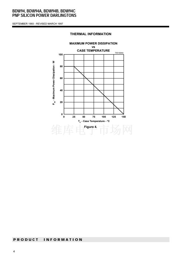
80 W at 25擄C Case Temperature
12 A Continuous Collector Current
Minimum h
FE
of 750 at 3 V, 5 A
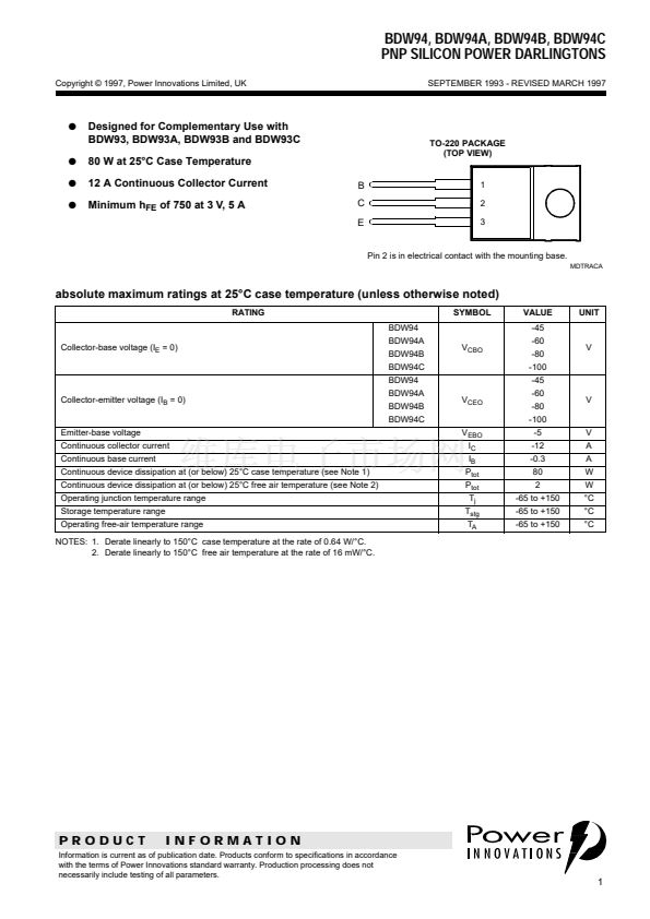
B
C
E
q
q
q
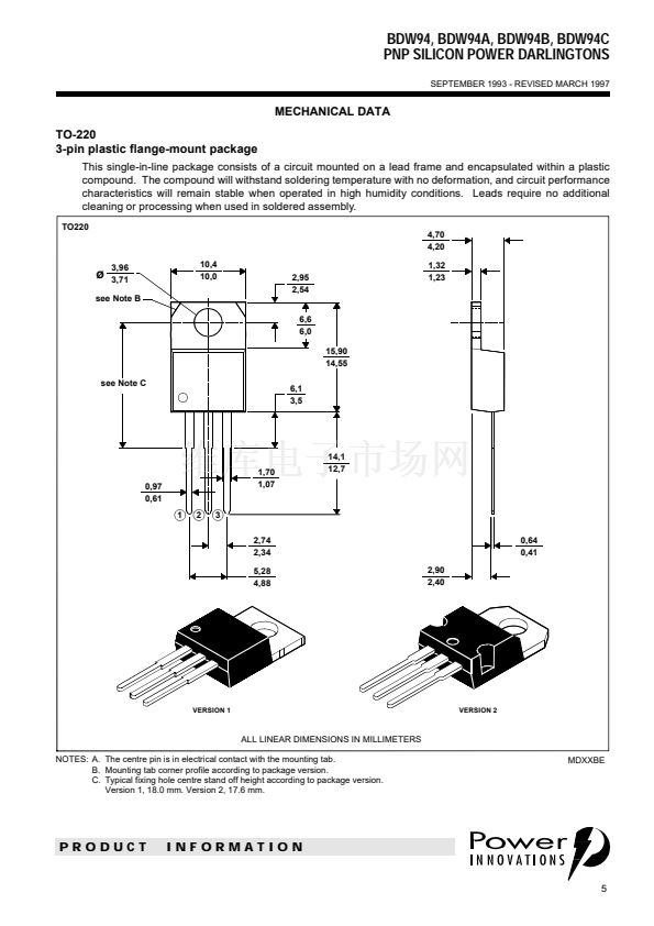
TO-220 PACKAGE
(TOP VIEW)
1
2
3
Pin 2 is in electrical contact with the mounting base.
MDTRACA
absolute maximum ratings
at 25擄C case temperature (unless otherwise noted)
RATING
BDW94
Collector-base voltage (I
E
= 0)
BDW94A
BDW94B
BDW94C
BDW94
Collector-emitter voltage (I
B
= 0)
BDW94A
BDW94B
BDW94C
Emitter-base voltage
Continuous collector current
Continuous base current
Continuous device dissipation at (or below) 25擄C case temperature (see Note 1)
Continuous device dissipation at (or below) 25擄C free air temperature (see Note 2)
Operating junction temperature range
Storage temperature range
Operating free-air temperature range
NOTES: 1. Derate linearly to 150擄C case temperature at the rate of 0.64 W/擄C.
2. Derate linearly to 150擄C free air temperature at the rate of 16 mW/擄C.
V
EBO
I
C
I
B
P
tot
P
tot
T
j
T
stg
T
A
V
CEO
V
CBO
SYMBOL
VALUE
-45
-60
-80
-100
-45
-60
-80
-100
-5
-12
-0.3
80
2
-65 to +150
-65 to +150
-65 to +150
V
A
A
W
W
擄C
擄C
擄C
V
V
UNIT
PRODUCT
INFORMATION
Information is current as of publication date. Products conform to specifications in accordance
with the terms of Power Innovations standard warranty. Production processing does not
necessarily include testing of all parameters.
1


 1
1
 2
2
 3
3
 4
4
 5
5
 6
6
