isolation and/or broadband operation. The GaAs MMIC
鈩?/div>
load
which is switched into the high isolation arm for low return
loss. Power consumption is very low, typically 75
碌A(chǔ)
at
-5 V. While recommended for operation up to 18 GHz, the
switch performs well through 22 GHz.
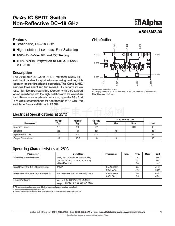
0.000
0.000
0.827
2.055
2.885
0.145
Dimensions indicated in mm.
All DC (V) pads are 0.1 x 0.1 mm and RF In, Out pads are 0.07 mm wide.
Chip thickness = 0.1 mm.
Electrical Specifications at 25擄C
Parameter
1
Insertion Loss
2
Isolation
Input Return Loss
Output Return Loss
2 GHz
Typ.
1.5
82
17
16
10 GHz
Typ.
2.8
57
8.5
10.5
18 GHz
Typ.
2.2
50
12.5
16
48
7
9
2, 10 and 18 GHz
Min.
Max.
3.0
Unit
dB
dB
dB
dB
Operating Characteristics at 25擄C
Parameter
1
Switching Characteristics
Condition
Rise, Fall (10/90% or 90/10% RF)
On, Off (50% CTL to 90/10% RF)
Video Feedthru
3
0/-5 V
For Two-tone Input Power +13 dBm
V
Low
= 0 to -0.2 V @ 20 碌A(chǔ) Max.
V
High
= -3 V to -6 V @ 250 碌A(chǔ) Max.
0.5鈥?8 GHz
0.001 GHz
0.5鈥?8 GHz
0.001 GHz
Frequency
Min.
Typ.
3
6
20
24
16
46
35
Max.
Unit
ns
ns
mV
dBm
dBm
dBm
dBm
Input Power for 1 dB Compression
Intermodulation Intercept Point (IP3)
Control Voltages
1. All measurements made in a 50
鈩?/div>
system, unless otherwise specified.
2. Insertion loss changes 0.003 dB/擄C.
3. Video feedthru measured with 1 ns risetime pulse and 500 MHz bandwidth.
Alpha Industries, Inc.
[781] 935-5150
鈥?/div>
Fax
[617] 824-4579
鈥?/div>
Email
sales@alphaind.com
鈥?/div>
www.alphaind.com
Specifications subject to change without notice. 7/00A
1


 1
1
 2
2
