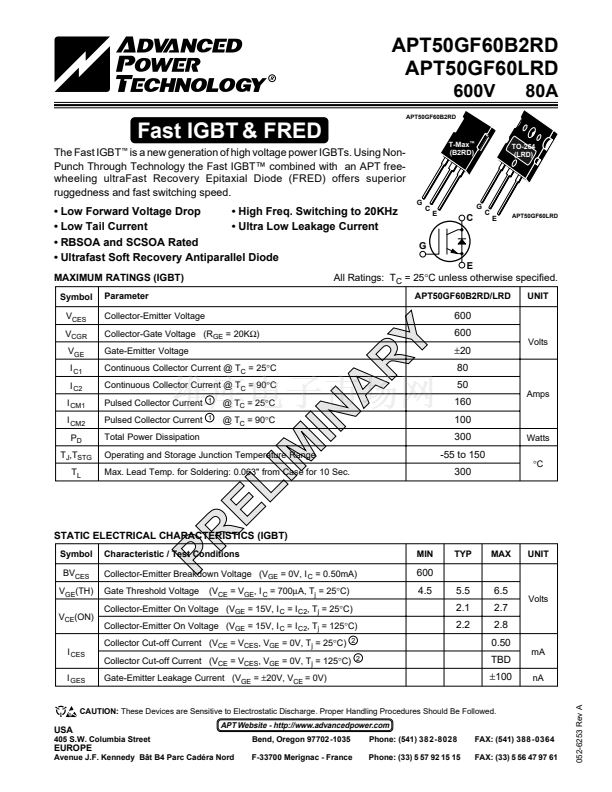
is a new generation of high voltage power IGBTs. Using Non-
ruggedness and fast switching speed.
鈩?/div>
(B2RD)
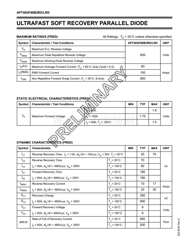
鈥?Low Forward Voltage Drop
鈥?High Freq. Switching to 20KHz
鈥?Low Tail Current
鈥?Ultra Low Leakage Current
鈥?RBSOA and SCSOA Rated
鈥?Ultrafast Soft Recovery Antiparallel Diode
MAXIMUM RATINGS (IGBT)
Symbol
V
CES
V
CGR
V
GE
I
C1
I
C2
I
CM1
I
CM2
P
D
T
J
,T
STG
T
L
Parameter
Collector-Emitter Voltage
C
G
E
C
C
E
APT50GF60LRD
G
E
APT50GF60B2RD/LRD
UNIT
All Ratings: T
C
= 25擄C unless otherwise specified.
600
RY
A
IN
MIN
Collector-Gate Voltage (R
GE
= 20K鈩?
Gate-Emitter Voltage
Continuous Collector Current @ T
C
= 25擄C
Continuous Collector Current @ T
C
= 90擄C
Pulsed Collector Current
Pulsed Collector Current
Total Power Dissipation
1
1
600
鹵20
80
50
160
100
300
-55 to 150
300
Watts
擄C
Amps
Volts
@ T
C
= 25擄C
@ T
C
= 90擄C
Operating and Storage Junction Temperature Range
Max. Lead Temp. for Soldering: 0.063" from Case for 10 Sec.
STATIC ELECTRICAL CHARACTERISTICS (IGBT)
Symbol
BV
CES
V
GE
(TH)
V
CE
(ON)
Characteristic / Test Conditions
Collector-Emitter Breakdown Voltage (V
GE
= 0V, I
C
= 0.50mA)
Gate Threshold Voltage
(V
CE
= V
GE
, I
C
= 700碌A(chǔ), T
j
= 25擄C)
TYP
MAX
UNIT
PR
EL
IM
600
4.5
5.5
2.1
2.2
6.5
2.7
2.8
0.50
mA
nA
052-6253 Rev A
Volts
Collector-Emitter On Voltage (V
GE
= 15V, I
C
= I
C2
, T
j
= 25擄C)
Collector-Emitter On Voltage (V
GE
= 15V, I
C
= I
C2
, T
j
= 125擄C)
Collector Cut-off Current (V
CE
= V
CES
, V
GE
= 0V, T
j
= 25擄C)
Collector Cut-off Current (V
CE
= V
CES
, V
GE
= 0V, T
j
= 125擄C)
Gate-Emitter Leakage Current (V
GE
=
鹵20V,
V
CE
= 0V)
2
2
I
CES
I
GES
TBD
鹵100
CAUTION:
These Devices are Sensitive to Electrostatic Discharge. Proper Handling Procedures Should Be Followed.
USA
405 S.W. Columbia Street
APT Website - http://www.advancedpower.com
Bend, Oregon 97702 -1035
F-33700 Merignac - France
Phone: (541) 382-8028
Phone: (33) 5 57 92 15 15
FAX: (541) 388-0364
FAX: (33) 5 56 47 97 61
EUROPE
Avenue J.F. Kennedy B芒t B4 Parc Cad茅ra Nord


 1
1
 2
2
 3
3
 4
4
 5
5
 6
6
 7
7
