Application Note 36
Micrel
Application Note 36
MIC4826/7 Electroluminescent Display Drivers
by William Mai and Andrew Cowell
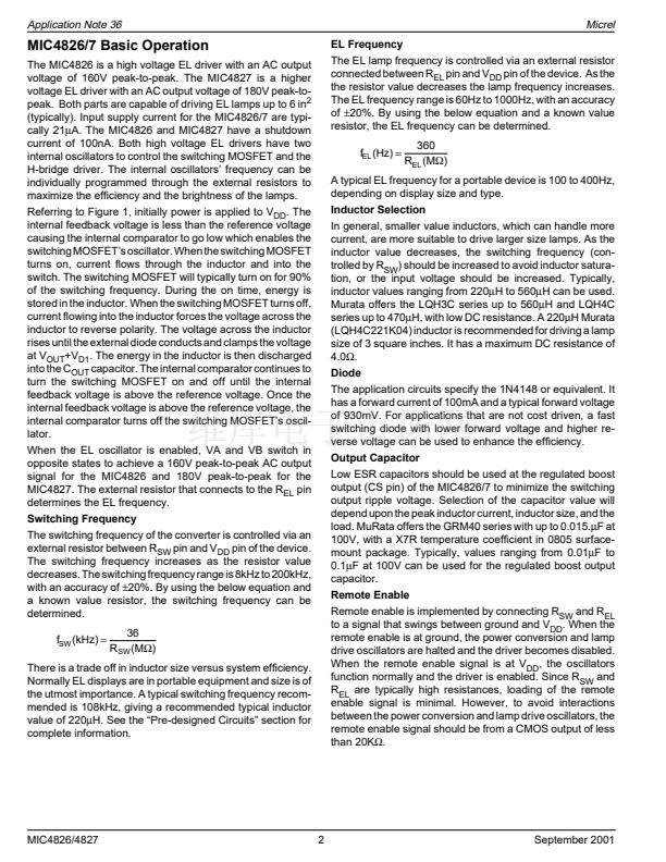
This application note covers the MIC4826/7 Electrolumines-
cent (EL) lamp drivers and designing with EL lamps.
With most phosphors, the spectrum of emitted light will tend
to shift towards blue with an increase in excitation frequency.
Color can be controlled by selecting the phosphor type, by
adding fluorescent dyes in the phosphor layer, by using a
color filter over the lamp, or a combination of these pro-
cesses. EL lamp brightness increases approximately with the
square of applied voltage. Increasing frequency, in addition
to affecting hue, will also increase EL lamp brightness, but
with a more linear relationship. Many EL lamp manufacturers
provide performance characteristics informing designers on
the relationships of frequency, voltage, and EL lamp bright-
ness for their EL lamps.
Increased voltage and/or frequency, however, adversely
affect lamp life. Higher frequencies generally decrease lamp
life moreso than increased voltages. EL lamps, unlike other
types of light sources, do not abruptly fail. Instead, their
brightness gradually decreases through use. Due to the
nature of the devices that EL lamps are used in, this is
normally not a concern.
The MIC4826 and MIC4827 allow the user to select the EL
frequency and voltage driving the lamp to give the user
maximum flexibility during the design process.
Transparent Front Protective Cover
Transparent Front Electrode
Phosphor
Dielectric
Rear Electrode
Rear Protective Cover
Electroluminescent Displays - The Basics
The design of an EL lamp circuit begins with the selection of
a lamp. A typical lamp will exhibit a capacitance on the order
of 2nF to 3.5nF per square inch. When a high voltage AC
signal is applied across the electrodes of an EL lamp, an
electric field is generated across the plates of the lamp. This
electric field excites the phosphor atoms to a higher energy
state. When the electric field is removed, the atoms fall back
to a lower energy state, emitting photons as visible light. The
wavelength of the emitted light is determined by the type of
phosphor used and the frequency of the excitation voltage.
Figure 1 shows a typical bridge configuration that is applied
to the EL electrodes to generate the AC signal. Typical AC
voltages applied to the EL lamp are 50V to 250 V
PK-PK
, with
a frequency of 50Hz to 1KHz.
V
IN
1
L1
220
m
H
V
DD
5
D1
C
IN
R
SW
2
SW
R
SW
Switch
Oscillator
Q
1
R
EL
Q
2
EL
Oscillator
Q
3
7
3
8
6
C
OUT
CS
VA
V
EL LAMP
V
REF
VB
Q
4
R
EL
Figure 3. Typical EL Lamp Construction
How the MIC4826/7 Drives the EL Display
To generate the high voltages needed for driving EL lamps,
MICREL drivers employ switch-mode converters using a
boost converter to generate the high voltages needed. Fol-
lowing the boost converter is an H-bridge driver, this applies
the peak-to-peak voltage across the EL lamp at a user
selectable frequency. The MIC4826 provides 160 V
PP
while
the MIC4827 provides 180V
PP
for bigger EL lamps. Figure 1
shows the internal block diagram of the MIC4826 and
MIC4827. The CS pin is the high voltage output of the boost
converter, which is half the peak-to-peak voltage across the
EL lamp. The second stage is the H-bridge circuit that
switches the boost voltage across the EL lamp. Both the
switching frequency of the boost converter and the switching
frequency of the EL lamp can be adjusted independently.
4
GND
Figure 1. MIC4826/7 Block Diagram
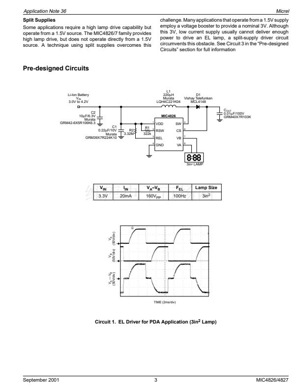
The basic AC signal applied to the EL lamp across VA and
VB, the two electrode pins, can be seen in Figure 2.
V
A
(50V/div)
V
A
鈥?V
B
(50V/div)
V
B
(50V/div)
V
IN
= 3.0V
L = 220碌H
C
OUT
= 0.01碌F
Lamp = 2in
2
R
SW
= 332k
R
EL
= 3.32M
TIME (2ms/div)
Figure 2. Typical AC Signal Applied to EL lamp
Micrel, Inc. 鈥?1849 Fortune Drive 鈥?San Jose, CA 95131 鈥?USA 鈥?tel + 1 (408) 944-0800 鈥?fax + 1 (408) 944-0970 鈥?http://www.micrel.com
September 2001
1
MIC4826/4827


 1
1
 2
2
 3
3
 4
4
 5
5
 6
6
 7
7
 8
8
