Application Note 28
Micrel
Application Note 28
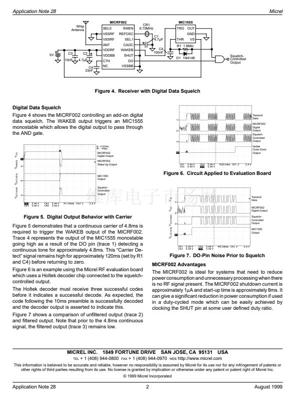
Data Squelch Using the MICRF002
By Sean Montgomery
Introduction
There are many new applications being created every day
which use low power radio as a link for simple remote
actuation such as garage doors, keyless entry, remote con-
trols etc... With the release of the Micrel MICRF001 RF
receiver and data demodulator IC, the design of such a link
has never been easier. Applications which implement this
Micrel receiver IC often require both low price and low power
consumption, with the digital functions, including data decod-
ing, often performed by low cost 4-bit microcontrollers.
As is common with all superheterodyne AM receivers, the
output will contain noise when there is no RF carrier present.
The operation of the AGC (automatic gain control) and the
demodulator in the MICRF001 converts very low level noise
into a corresponding logic level output noise. This output
noise combined with the relatively low processing power of
the 4-bit microcontroller consequently takes up a great deal
of the processing time which could be better spent on other
functions. There are two ways in which this problem can be
addressed: introducing analog squelch and introducing digi-
tal squelch.
Digital Squelch
Introduction to MICRF002 Features
The MICRF002 includes two important features that differen-
tiate it from the MICRF001 and MICRF011:
Shutdown
(SHUT) allows duty-cycled operation to extend
battery life in battery operated systems.
Wake up
(WAKEB) operates as a simple data-preamble
detector output and can be used to interrupt a microcontroller.
If only one microcontroller input is available, it can be used as
a control signal for a digital data squelch circuit.
~6.75MHz
Reference
Oscillator
Demodulated
Data
256
128-Bit
Counter
WAKEB
(active low)
Analog Squelch
Adding a small offset to the C
TH
pin can prevent noise from
producing logic-level transitions at the data output. Since we
have now added a signal path attenuation, the range will be
somewhat reduced.
Signal from
peak detector
R
SC
鈥淧robe A鈥?/div>
C
TH
鈥淧robe B鈥?/div>
Signal Level
Figure 2. Simplified Wake-Up Block Diagram
To utilize the wake-up function, an uninterrupted 5ms must be
transmitted at the start of each data word, or a single 5ms
carrier at the start of the data pattern. (Sending carrier at the
start of each data word is recommended as it improves
communication reliability). When uninterrupted carrier is de-
tected for 128 clock cycles of the nominal 26.4kHz clock,
WAKEB will transition low and stay low until data begins.
This output can be used directly by the microcontroller if there
is an available I/O pin. Alternatively, we can use some
discrete circuitry to effectively 鈥榝ilter鈥?the data output. The
following discusses a possible solution for this function.
MICRF002
Whip
Antenna
SEL0
VSSRF
VSSRF
ANT
VDDRF
5V
C3
10nF
C2
4.7碌F
C4
33nF
VDDBB
CTH
NC
SWEN
REFOSC
SEL1
CAGC
WAKEB
SHUT
DO
VSSBB
Interrupt
Data Output
CR1
6.75MHz
C1
4.7碌F
Background Noise
(Probe A)
modified
slicing level
slicing level
Unmodified
Output
Time
Demodulated
Background Noise
(Probe B)
logic-high
Time
Modified
Output
Demodulated
Background Quiet
(Probe B)
logic-high
Time
Figure 3. Receiver with Data and Interrupt Outputs
WAKEB can be connected directly to a microcontroller input
pin and used as an enable signal (interrupt) for the
microprocessor鈥檚 data input as shown in Figure 3.
Figure 1. Adding Offset (Analog Squelch)
QwikRadio is a trademark of Micrel, Inc. The QwikRadio ICs were developed under a partnership agreement with AIT of Orlando, Florida
Micrel, Inc. 鈥?1849 Fortune Drive 鈥?San Jose, CA 95131 鈥?USA 鈥?tel + 1 (408) 944-0800 鈥?fax + 1 (408) 944-0970 鈥?http://www.micrel.com
August 1999
1
Application Note 28


 1
1
 2
2
