place in the modern home. Since many homes have more
located near the most used television. Consider that it may
its IR remote control is unusable (see Figure 1).
control and converts it to an RF signal. The RF signal is
received and the data is demodulated and output. The
controller inputs.
signal and converts it to an RF data signal.
220鈩?/div>
TX1
C2
2.5pF鈥?pF
INFRARED
V
S
5V
C1
4.7碌F
TV
Set-Top Box
Feeds Both TVs
Figure 3. IR Receiver to RF Transmitter
Figure 1. Radio Link Between Rooms
An ideal solution is to replace the IR remote control with a low-
power RF (radio frequency) data link to overcome IR鈥檚 line-
of-site restriction. Because it may not be practical to replace
the existing IR remote control system, another solution is to
create a RF data link that allows the use of the existing IR
controller.
Figure 2 shows a block diagram of the approach which is
taken. The following test circuits will demonstrate the opera-
tion of this system up to the RF receiver鈥檚 demodulated data
output. The IR data modulator and transmitter is not pre-
sented here.
RF
5V
10nF
4.7碌F
IR1 is a Temic TFMS2409 photomodule for PCM remote
control; TX1 is a LPRS (Low Power Radio Solutions) LQ-
TX433A-S 433.92MHz SAW-based microtransmitter mod-
ule.
MICRF001 RF Receiver
Figure 4 shows a receiver design based on the MICRF001 IC.
Signal and no-signal conditions are shown in Figures 5 and
6 respectively.
MICRF001
Whip
Antenna
SEL0
VSSRF
VSSRF
ANT
VDDRF
VDDBB
CTH
33nF
SWEN
REFOSC
SEL1
CAGC
VSSBB
VSSBB
DO
Receive
Data
C1
4.7碌F
CR1
3.36MHz
Low-Power
Transmiter
IR Receiver/
Demodulator
IR
RF Receiver/
Demodulator
IR Encoder/
Transmitter
Figure 4. RF Receiver with Data Output
IR
Infrared
Remote Control
Set-Top
Box
Figure 2. System Block Diagram
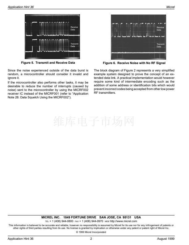
Figure 5 confirms that the data is reproduced correctly. There
is a 100碌s delay from transmit data rising edge to receive data
rising edge.
Without a signal, Figure 6 shows output transitions corre-
sponding to random RF noise received at the antenna. This
output noise is typical of superheterodyne AM receivers
without data squelch circuits. This output noise is expected to
be at logic levels as a result of the receiver IC鈥檚 AGC
(automatic gain control) and demodulation circuitry.
QwikRadio is a trademark of Micrel, Inc. The QwikRadio ICs were developed under a partnership agreement with AIT of Orlando, Florida
Micrel, Inc. 鈥?1849 Fortune Drive 鈥?San Jose, CA 95131 鈥?USA 鈥?tel + 1 (408) 944-0800 鈥?fax + 1 (408) 944-0970 鈥?http://www.micrel.com
August 1999
1
Application Hint 36


 1
1
 2
2
