廬
USING THE CONTINUOUS PARALLEL MODE WITH THE
ADS7824 AND ADS7825
By Bonnie C. Baker
1
The ADS7824 and ADS7825 are 12-bit and 16-bit converters
that have a four channel multiplexed front end. The channel
selection on the analog input of these converters is program-
mable by way of the pins on the devices, A0 and A1 (see Table
I). This feature provides the most flexibility by allowing the
user to change to the preferred input channel on the fly.
Additionally, the input channels can be cycled by utilizing the
continuous mode of the converter. This mode is easily enabled
by tying the CONTC pin high. In this mode, acquisition and
conversions will take place continually, cycling through all
four input channels without user intervention.
In the serial mode (PAR/SER = LOW), the continuous mode
(enabled with CONTC = HIGH) will cause the device to
acquire and converter the input signal and cycle through all
A0
0
0
1
1
0
A1
0
1
0
1
0
CONTC
0
0
0
0
1
DESCRIPTION
Enables AIN
0
. A0 and A1 are configured as input pins and the user provides instructions to the device to determine which
input will be accessed. This channel address is updated just before BUSY rises.
Enables AIN
1
. A0 and A1 are configured as input pins and the user provides instructions to the device to determine which
input will be accessed. This channel address is updated just before BUSY rises.
Enables AIN
2
. A0 and A1 are configured as input pins and the user provides instructions to the device to determine which
input will be accessed. This channel address is updated just before BUSY rises.
Enables AIN
3
. A0 and A1 are configured as input pins and the user provides instructions to the device to determine which
input will be accessed. This channel address is updated just before BUSY rises.
Enables AIN
0
. A0 and A1 are configured as output pins. A0 and A1 cycle sequentially from one channel to the next as long
as CONTC is HIGH. The channel that is being acquired or converted is output on these address lines. Data is valid for the
pervious channel. These channels are updated when BUSY rises.
Enables AIN
1
. A0 and A1 are configured as output pins. A0 and A1 cycle sequentially from one channel to the next as long
as CONTC is HIGH. Then channel that is being acquired or converted is output on these address lines. Data is valid for the
previous channel. These channels are updated when BUSY rises.
Enables AIN
2
. A0 and A1 are configured as output pins. A0 and A1 cycle sequentially from one channel to the next as long
as CONTC is HIGH. The channel that is being acquired or converted is output on these address lines. Data is valid for the
previous channel. These channels are updated when BUSY rises.
Enables AIN
3
. A0 and A1 are configured as output pins. A0 and A1 cycle sequentially from one channel to the next as long
as CONTC is HIGH. The channel that is being acquired or converted is output on these address lines. Data is valid for the
previous channel. These channels are updated when BUSY rises.
four channels continually as long as CS, R/C and PWRD are
LOW (see Table II). Selection as to which input channel will
be accessed first is done with either the PWRD function or the
CONTC pin. If PWRD is cycled, the first channel that will be
acquired will be channel 0, AIN
0
. If CONTC is cycled, the
register does not change and the current channel becomes the
first in the sequence. When CONTC is HIGH, A0 and A1
address inputs become outputs. When BUSY rises at the end
of a conversion, A0 and A1 will output the address of the
channel that will be converted next. Additionally, data will be
valid for the previous channel after BUSY rises. See Table II
and Figure 1 for channel selection timing in the continuous,
serial conversion mode.
0
1
1
1
0
1
1
1
1
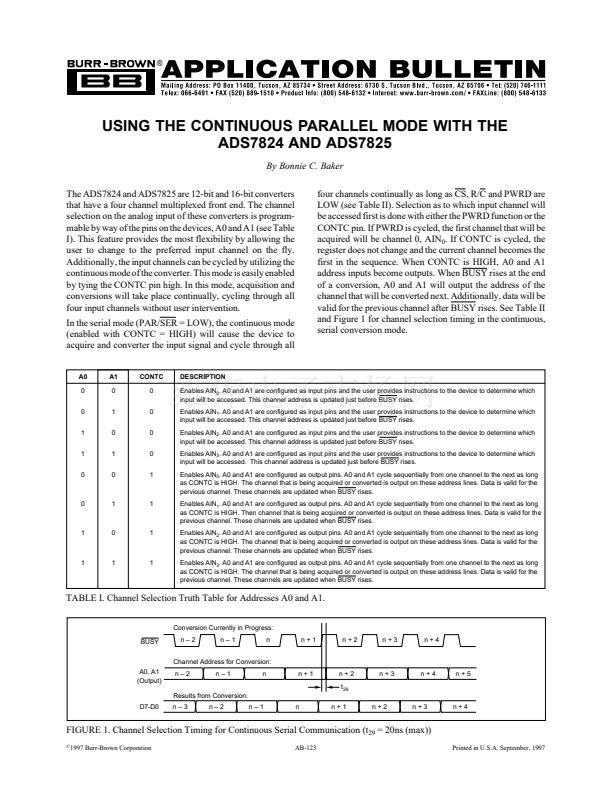
TABLE I. Channel Selection Truth Table for Addresses A0 and A1.
Conversion Currently in Progress:
BUSY
n鈥?
n鈥?
n
n+1
n+2
n+3
n+4
Channel Address for Conversion:
A0, A1
(Output)
n鈥?
n鈥?
n
n+1
n+2
t
29
Results from Conversion:
D7-D0
n鈥?
n鈥?
n鈥?
n
n+1
n+2
n+3
n+4
n+3
n+4
n+5
FIGURE 1. Channel Selection Timing for Continuous Serial Communication (t
29
= 20ns (max))
漏
1997 Burr-Brown Corporation
AB-123
1
Printed in U.S.A. September, 1997


 1
1
 2
2
 3
3
