鈭單?/div>
A/D CONVERTERS
By Bonnie C. Baker
1
Many of the delta-sigma Analog-to-Digital converters in
Burr-Brown鈥檚 product line come in pairs, where one is a
single channel differential input converter and the second is
a four channel differential input converter. This is true for
the ADS1210 and ADS1211. The ADS1210 has one differ-
ential input, where the ADS1211 has four differential inputs
(as shown in Figure 1). Another similar pair in the Burr-
Brown product line is the ADS1212 (one differential input)
and the ADS1213 (four differential inputs). In the case of the
ADS1211 and ADS1213, the four channel input capability is
implemented internally with a analog multiplexer input
stage followed by a single programmable gain amplifier
stage and a second-order modulator. At the end of the signal
path a third-order digital filter is used to refine the accuracy
to 23 bits for the ADS1210 and ADS1211 and 19 bits for the
ADS1212 and ADS1213.
Multiplexing signals at the input of A/D converters is not a
new technique, however, the combination of modulator
stage and digital filter in these products offer challenging
synchronization problems. In simple terms, the modulator
stage continually samples the input signal and changes it to
a steady stream of ones and zeros. The stream of ones and
zeros is then sampled and brought into the digital filter
section in a FIFO manner. The digital filter implements a
moving average algorithm on block of the bits contained in
its registers. The results of the digital averaging calculation
is presented at the output of the A/D converter as one
conversion. The digital filter that is designed in the ADS1210,
ADS1211, ADS1212, and ADS1213 is a third order FIR
filter and calculates a weighted average of three consecutive
conversions; the current conversion data which is most
heavily weighted and was modulated three conversions
prior, the next conversion data which was modulated two
conversions prior and the modulator data that was most
recently modulated which is the most lightly weighted data.
This method of achieving high accuracies of 19 bits
(ADS1212 and ADS1213) or 23 bits (ADS1210 or ADS1211)
has little impact if the analog input signal is slow changing.
A worst case scenario is where the input signal jumps from
minus full scale to plus full scale as a step function. This can
easily occur if a multiplexer is used at the input of the
device. The advantage of having internal multiplexers, as is
3
4
AGND AV
DD
REF
OUT
REF
IN
V
BIAS
X
IN
X
OUT
MODE
A
IN
1P
A
IN
1N
A
IN
2P
A
IN
2N
A
IN
3P
A
IN
3N
A
IN
4P
A
IN
4N
MUX
A
IN
P
+2.5V
Reference
+3.3V Bias
Generator
Clock Generator
DGND
DV
DD
Micro Controller
Second-Order
鈭嗏垜
Modulator
Third-Order
Digital Filter
Instruction Register
Command Register
Data Output Register
Offset Register
Full-Scale Register
SCLK
SDIO
SDOUT
PGA
A
IN
N
Modulator Control
Serial Interface
ADS1211 Only
ADS1210/11
DSYNC
CS
DRDY
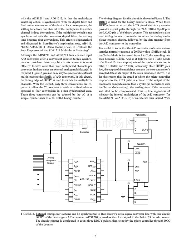
FIGURE 1. The circuit topology of the delta-sigma converter line from Burr-Brown, including the ADS1210, ADS1211,
ADS1212, and ADS1213 is shown here. The ADS1211 and ADS1213 have internal, four channel analog
multiplexers added to their front end.
漏
1997 Burr-Brown Corporation
AB-116
1
Printed in U.S.A. June, 1997


 1
1
 2
2
 3
3
