廬
APPLICATION BULLETIN
Mailing Address: PO Box 11400 鈥?Tucson, AZ 85734 鈥?Street Address: 6730 S. Tucson Blvd. 鈥?Tucson, AZ 85706
Tel: (602) 746-1111 鈥?Twx: 910-952-111 鈥?Telex: 066-6491 鈥?FAX (602) 889-1510 鈥?Immediate Product Info: (800) 548-6132
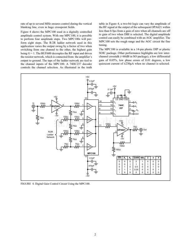
THE MPC100 ANALOG MULTIPLEXER IMPROVES
RF SIGNAL DISTRIBUTION
By Christian Henn
When designing high-performance systems for RF and video
applications requiring amplifiers, multiplexers, DC restora-
tion circuits, switched and continuous multipliers, or pro-
grammable gain amplifiers, finding the right component to
do the job is not easy. The new 4 to 1 video multiplexer
MPC100 opens the door to high-speed signal distribution
without the headaches. This component contains four
wideband open-loop amplifiers connected together inter-
nally at the output with a bandwidth of 180MHz at 1.4Vp-
p signal swing. When the user selects one channel by
applying a digital 鈥?鈥?to the corresponding SEL input (see
Figure 1), the component acts as a buffer amplifier with a
high input impedance of 0.88M鈩|1pF and a low output
impedance of 11鈩?
The MPC100 can be used to design a bus-controlled distri-
bution field, as shown in Figure 3. In this application, a
driver device, which is controlled by a memory and a
parallel-to-serial converter, shifts the information about the
field state into the output latches, U
1
, U
2
, and U
3
. When the
strobe line is triggered the new latch information is stored in
the output latches, which controls whether the buffers of the
MPC100 (U4-U9) are in an 鈥渙n鈥?or 鈥渙ff鈥?state. The MPC100
operates with a fast make-before-break switching action to
keep the output switching transients small and short. As
shown in Figure 2, the switching time from one channel to
the next is less than 0.5碌s, and the signal envelope during
transition rises and falls symmetrically and shows practi-
cally no overshoot or DC settling effects. A transmission
SWITCHING ENVELOPE
IN
1
IN
2
IN
3
IN
4
1
3
5
7
DB1
DB2
11
DB3
DB4
V
OUT
14
13
9
8
SEL
1
SEL
2
SEL
3
SEL
4
Time (碌s)
FIGURE 1. MPC100 Wide Bandwidth 4
X
1 Video Multi-
plexer.
FIGURE 2. Switching Time from Channel to Channel of the
MPC100.
MPC100
SEL Inputs
1
4
SER IN
2
0
3
CLOCK
STR
OE
1
3
5
5
6
7
1
MPC100
SEL Inputs
3
5
7
SER 9
Out
2
3
1
4
Output Voltage (V)
MPC100
SEL Inputs
3
5
5
6
7
1
MPC100
SEL Inputs
3
5
7
SER 9
Out
7 14 13 12 11
Parallel Out
HC4094
15
7 14 13 12 11
Parallel Out
HC4094
1
15
FIGURE 3. Serial Bus-controlled Distribution Field Using the MPC100.
漏
1993 Burr-Brown Corporation
AB-049
Printed in U.S.A. March, 1993


 1
1
 2
2
