Mailing Address: PO Box 11400 鈥?Tucson, AZ 85734 鈥?Street Address: 6730 S. Tucson Blvd. 鈥?Tucson, AZ 85706
Tel: (602) 746-1111 鈥?Twx: 910-952-111 鈥?Telex: 066-6491 鈥?FAX (602) 889-1510 鈥?Immediate Product Info: (800) 548-6132
either on the chip or a external capacitor provided by the user.
measurements, and a CT scanner front end. In Figure 1, 1/2 of
output signal. The transfer function of the integrator is:
= 鈥?/div>
1
C
INT
t
I dt + constant
0
IN
hold switch. The slew rate is specified at 1V/碌s minimum.
If the user has an input device that supplies a higher
maximum positive current, an external capacitor can be
added to comply with the slew rate specification of the
operational amplifier and the input signal can be connected
to the 鈥淚n鈥?pin, bypassing the hold switch.
The hold and reset switches are used to control the ACF2101.
Three basic modes of operation are controlled by these
switches. In the integrate mode, the output voltage integrates
from 0 to 鈥?0V. In the hold mode, the output voltage is held
at the present level. In the reset mode, the output returns to
zero so the integration cycle can start again. The switching
diagram for these modes are shown in Figure 2. The output
of the ACF2101 is selectable by use of the select switches,
which can be used to multiplex the outputs when multiple
integrators are connected to a common bus. The internal
capacitor (C
F
) can be used alone or in parallel with an
external capacitor (C
OPT
). In addition, the external capacitor
can be used without the internal capacitor if needed.
where C
INT
= integration capacitor
I
IN
= positive input current
constant = initial voltage at output
Assuming that the initial voltage at the output of the integra-
tor is 0V, the transfer function becomes:
1
t
I
IN
dt
V
OUT
= 鈥?/div>
C
INT
0
The ACF2101 is specified for a maximum input current of
100碌A(chǔ). The input current magnitude is limited by the slew
rate of the operational amplifier and by the resistance of the
0
Output (V)
Hold
Integrate
Hold RST Hold
Integrate
C
OPT(1)
C
INT
= C
F
+ C
OPT
鈥?0
Cap
C
F
100pF
In
I
IN
Sw In
Hold
Reset
Select
Sw
Out
INA120
Com
Sw
Instrumentation
Com
Amplifier
NOTE: (1) C
OPT
is an optional capacitor used for I
IN
>
100碌A(chǔ).
1/2 ACF2101
Off
Out
Hold
On
Off
Reset
On
Modes of Operation
SWITCH
Hold Switch
Reset Switch
MODE OF OPERATION
Integrate
Hold
Reset
ON
OFF
OFF
OFF
ON/OFF
ON
To
ADC
ON: Switch shorted; Logic 鈥?鈥?input. OFF: Switch open; Logic 鈥?鈥?input.
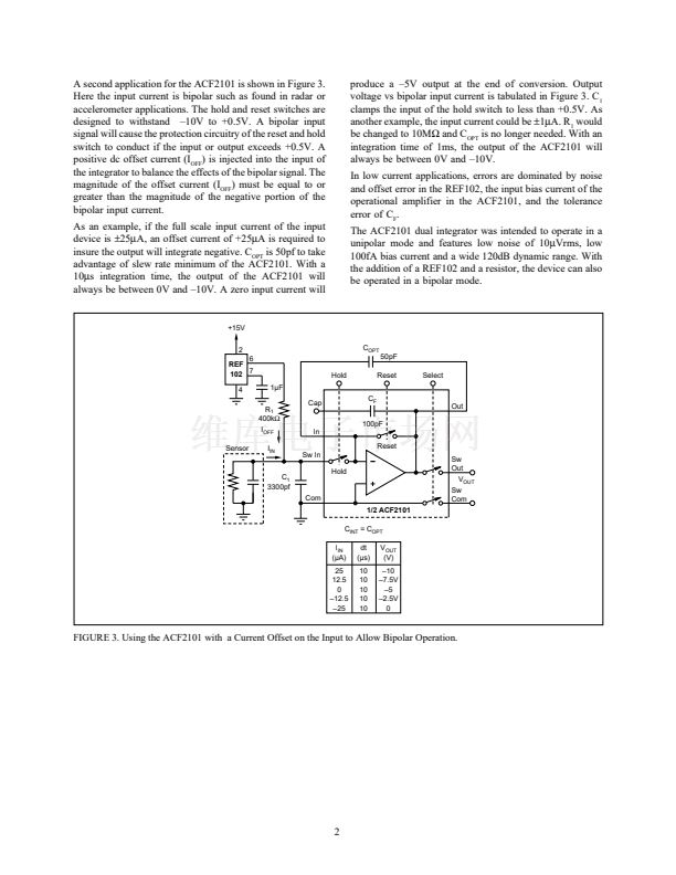
FIGURE 1. A Typical Application for the ACF2101 Switched
Integrator.
FIGURE 2. Modes of Operation for the ACF2101.
漏
1993 Burr-Brown Corporation
AB-048
Printed in U.S.A. March, 1993


 1
1
 2
2
