廬
APPLICATION BULLETIN
Mailing Address: PO Box 11400 鈥?Tucson, AZ 85734 鈥?Street Address: 6730 S. Tucson Blvd. 鈥?Tucson, AZ 85706
Tel: (602) 746-1111 鈥?Twx: 910-952-111 鈥?Telex: 066-6491 鈥?FAX (602) 889-1510 鈥?Immediate Product Info: (800) 548-6132
NOISE SOURCES IN APPLICATIONS USING
CAPACITIVE COUPLED ISOLATED AMPLIFIERS
By Bonnie C. Baker (602) 746-7984
Noise is a typical problem confronting many isolation appli-
cations. Isolation products such as analog isolation amplifi-
ers, optocouplers, transformers and digital couplers, are used
in applications to transmit signals across a high voltage
barrier while providing galvanic separation between two
grounds. Burr-Brown鈥檚 isolated analog amplifiers and digi-
tal couplers use one of three coupling technologies in their
isolation products, each having its own set of advantages and
disadvantages in noisy environments. These technologies
are inductive coupling, capacitive coupling and optical cou-
pling. Isolation amplifiers and digital couplers are used for
a variety of applications including breaking of ground loops,
motor control, power monitoring and protecting equipment
from possible damage. An understanding of the design
techniques used to transmit signals across the isolation
barrier, as well as an understanding of the sources of noise,
allows the users to quickly identify design and layout prob-
lems and make appropriate changes to reduce noise to
tolerable levels.
Noise is defined in this application note as a signal that is
present in a circuit other than the desired signal. This
definition excludes analog nonlinearities which may pro-
duce distortion. As shown in Figure 1, there are three
primary types of noise endemic to isolation applications,
each with their own set of possible solutions. The first noise
source is device noise. Device noise is the intrinsic noise of
the devices in the circuit. Examples of device noise would be
the thermal noise of a resistor or the shot noise of a
transistor. A second source of noise that effects the perfor-
mance of isolation devices is conductive noise. This type of
noise already exists in the conductive paths of the circuit,
such as the power lines, and mixes with the desired electrical
signal through the isolation device. The third source of noise
is radiated noise. Radiated noise is emitted from EMI sources
such as switches or motors and coupled into the signal. This
application bulletin will cover these three noise classifica-
tions as they relate to capacitive coupled isolation amplifi-
ers.
THEORY OF OPERATION OF THE
CAPACITIVE COUPLED ISOLATION AMPLIFIERS
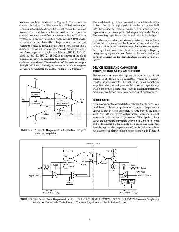
The capacitive coupled isolation amplifiers are designed
with an input and output section galvanically isolated by a
pair of matched capacitors. A block diagram of this type of
N
C
Power Supply
Noise
Isolated Side
Isolation
Amplifier
N
C
N
D
Spectral
Noise
+V
S2
N
D
鈥揤
S2
GND
2
N
C
+V
S1
Isolation
Barrier
N
C
Power Supply
Noise
System Side
Ripple
Noise
Electric Field
Coupling (EMI), N
R
N
C
Power Supply
Noise
鈥揤
S1
GND
1
Electric Field
Coupling (EMI), N
R
N
C
Power Supply
Noise
N
D
: Device Noise
N
C
: Conducted Noise
N
R
: Radiated Noise
Transient
Noise
FIGURE 1. The Three Basic Types of Noise in Isolation Applications are Device Noise, Conducted Noise, and Radiated Noise.
漏
1993 Burr-Brown Corporation
AB-047
Printed in U.S.A. April, 1993


 1
1
 2
2
 3
3
 4
4
 5
5
 6
6
 7
7
 8
8
