750鈩?/div>
6
(1)
Even though there is gain in the feedback of the INA105, the
circuit is stable as shown by the small-signal response of the
amplifier as seen in the scope photo, Figure 5. Since a unity-
gain difference amplifier operates in a noise gain of two,
gain can be added in its feedback loop without causing
instability with the following restrictions: 1) the added gain
is less than 2V/V, 2) the op amp in the difference amplifier
is unity gain stable, and 3) the phase shift added by the gain
buffer is low at the unity gain frequency of the op amp. All
stability requirements are met when using the INA105.
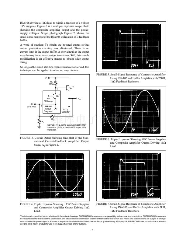
To understand the details of the composite amplifier, con-
sider the block diagram, Figure 2. Resistors R
1
and R
2
set the
gain of the buffer amplifier A
2
. The buffer amplifier is a
current-feedback op amp formed from the output transistors
in the INA105 and the external transistors, Q
1
and Q
2
. The
current feedback amplifier gives wide bandwidth and low
phase shift. Figure 3 shows one of two complementary
current-feedback amplifiers formed from the NPN output
transistor in the INA105 and the external PNP transistor, Q
1
.
This current-feedback amplifier section is active for positive
swings of the composite amplifier output. A complementary
current-feedback amplifier, using external transistor Q
2
, is
active for negative output swings of the composite amp.
Q1
2N3906
鈥揑n
A
1
+In
INA105
A
2
V
O
V
O
R
1
1000鈩?/div>
R
1
1000鈩?/div>
R
2
750鈩?/div>
+In
3
R
3
R
4
1
NOTE: Gain of the boost circuit is approximately 1 + R
2
/R
1
.
Q2
2N3904
4
R
4
200鈩?/div>
鈥?5V
NOTES: (1) R
2
= 750鈩?for INA105. R
2
= 1k鈩?for INA106 on
鹵12V
to
鹵18V
power supplies. R
2
= 2k鈩?for INA106 on
鹵8V
to
鹵18V
power supplies.
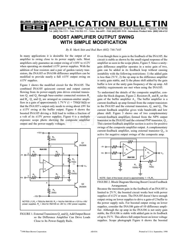
FIGURE 1. External Transistors Q
1
and Q
2
Add Output Boost
so the Difference Amplifier Can Drive Loads
Close to Its Power-Supply Rails.
FIGURE 2. Block Diagram Showing Boost Circuit Feedback
Arrangement.
Because the maximum gain in the feedback of an INA105 is
limited to 2V/V, the boosted circuit works best with power
supplies of
鹵12V
or more. The INA105 doesn鈥檛 have enough
output swing on lower supplies to drive a gain-of-2 buffer to
the power supply rails. For boosted output swing on lower
supplies, consider the INA106 gain-of-10 difference ampli-
fier. Although the op amp in the INA106 is not unity gain
stable, the INA106 is stable with added gain in its feedback
of up to 3V/V. This allows full output boost on lower voltage
supplies. Scope photograph Figure 6 shows the boosted
漏
1990 Burr-Brown Corporation
AB-016
Printed in U.S.A. September, 1990


 1
1
 2
2
