廬
APPLICATION BULLETIN
Mailing Address: PO Box 11400 鈥?Tucson, AZ 85734 鈥?Street Address: 6730 S. Tucson Blvd. 鈥?Tucson, AZ 85706
Tel: (520) 746-1111 鈥?Twx: 910-952-111 鈥?Telex: 066-6491 鈥?FAX (520) 889-1510 鈥?Immediate Product Info: (800) 548-6132
SINGLE-SUPPLY OPERATION OF ISOLATION AMPLIFIERS
By Rod Burt and R. Mark Stitt (602) 746-7445
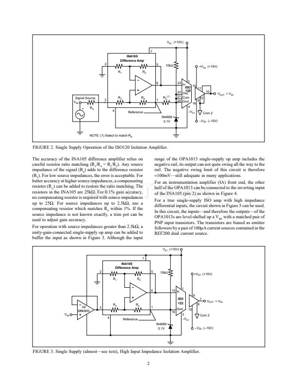
For simplicity, many systems are designed to operate from a
single external power supply. In battery powered systems
such as aircraft and automotive, it鈥檚 often a requirement.
Isolation amplifiers such as the ISO120 and ISO122 can be
easily modified for input side single-supply operation with
the addition of an INA105 difference amplifier. With ISO
amps, it鈥檚 the isolated input side power supply which most
often needs to be single supply. The output side of the ISO
amp uses a split
鹵15V
power supply, allowing a full
鹵10V
output swing.
The difference amplifier has advantages as compared to
traditional single-supply amplifiers. The inputs of a differ-
ence amplifier can swing to both the positive and negative
power-supply rails. In fact, in the application shown in
Figures 1 and 2, the input range of the circuit extends
approximately 2V below ground (the negative power supply
rail). This is because the resistors internal to the INA105
divide the input level in half as seen by the op amp.
The technique is illustrated in Figures 1 and 2 using the
ISO120 and ISO122. These ISO amps are specified for
operation from dual supplies as low as
鹵4.5V
and can be
operated with a total single power supply voltage as low as
9V. The circuit shown is designed for operation from a single
+15V power supply. This allows a 0V to +5V input range.
The most common application is for a single ended input
referred to ground as shown. For a differential input, pin 2
can be connected to a second input instead of ground. This
provides a 0V to 5V differential input with common-mode to
either rail.
To understand how the circuit works, consider the operation
of the INA105 difference amplifier. The difference amplifier
forces its output (pin 6) relative to its reference (pin 1) to be
equal to the differential input (pin 3 鈥?pin 2). The difference
amplifier reference pin and the ISO amp common are held at
approximately 5.1V by the 10k鈩?resistor and the zener
diode. This pseudo ground establishes an arbitrary accept-
able operating point for the ISO amp. The difference ampli-
fier then translates its input, relative to true ground, up to the
5.1V pseudo ground. In other words, a 0V to 5V input
between pins 3 and 2 of the INA105 is seen as a 0V to 5V
signal at the ISO amp input.
Isolated power is often at a premium and both the ISO120/
122 and the INA105 operate on relatively low power. Com-
mon zener diodes, on the other hand, may require several mA
for proper operation. The 1N4689 zener diode specified is a
low level type designed for applications requiring low oper-
ating currents. It has a sharp breakdown voltage specified at
a low 50碌A(chǔ).
V
S1
(+15V)
7
INA105
Difference Amp
2
R
1
R
2
6
15 In
1
9
Signal Source
V
IN
+
R
S
R
3
R
4
(1)
R
C
5
10k鈩?/div>
+V
S2
(+15V)
ISO
122
Gnd
16
10
7
8
V
OUT
= V
IN
3
4
1
Reference
IN4689
5.1V
2
鈥揤
S1
Com 2
鈥揤
S2
(鈥?5V)
NOTE: (1) Select to match R
S
.
FIGURE 1. Single Supply Operation of the ISO122 Isolation Amplifier.
16
漏
1990 Burr-Brown Corporation
1
AB-009A
Printed in U.S.A. August, 1991


 1
1
 2
2
 3
3
 4
4
