3UA Thermally Delayed Overload Relays
CLASS 10
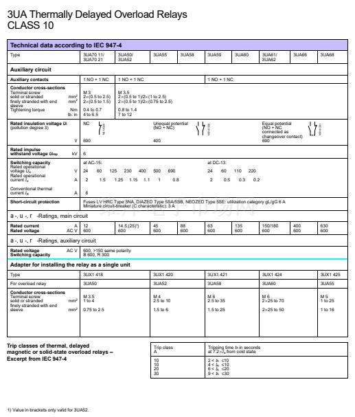
Technical data according to IEC 947-4
Type
Trip class
Phase failure sensitivity by
differential phase shift
Changeover to automatic
reset
RESET button with trip-free
feature
Temperature compensation
Switch position indicator
Test button
actuates the NO
and NC contacts
Terminal for contactor coil
Permissible ambient
temperature
Degree of protection
Shock resistance
擄C
3UA70 11/
3UA70 21
3UA50/
3UA52
3UA55
3UA58
3UA59
3UA60
3UA61/
3UA62
3UA66
3UA68
CLASS 10A (2 s <
t
A
鈮?0
s at 7.2
脳I
e
from cold state and
t
A
鈮?
min at 1.5
脳I
e
from hot state)
yes
no
yes
yes
yes
yes
no
1
)
鈥?5 to +55
2
)
yes
yes
yes
yes
yes
yes
yes
鈥?5 to +55
yes
yes
yes
yes
yes
yes
yes
yes
yes
yes
yes
yes
yes
no
1
)
yes
yes
yes
yes
yes
yes
no
1
)
yes
yes
yes
yes
yes
yes
no
1
)
yes
yes
yes
yes
yes
yes
no
1
)
yes
yes
yes
yes
yes
yes
no
1
)
yes
yes
yes
yes
yes
yes
no
1
)
IP 00/open or IP 20 to IEC 947-1 and DIN 40 050
g
/ms
8/10
Main circuit
Rated insulation
voltage
U
i
(pollution degree 3)
AC/DC V
690
690
690
1000
690
1000
1000
1000
1000
Rated impulse
withstand voltage
U
imp
Type of current,
frequency range
Conductor cross-sections
kV
6
6
6
8
6
8
8
8
8
DC; AC up to 400 Hz
AC 50 to 400 Hz
Setting
range
(鈮?00 A/
>200 A)
Terminal screw
solid or stranded
finely stranded with end
sleeve
Flat bars
Tightening torque
mm
2
mm
2
mm
Nm
lb. in
Nm
lb. in
M3
0.5 to 2.5
0.5 to 1.5
鈥?/div>
0.4 to 0.7
4 to 6.5
M4
2.5 to 6
1.5 to 4
鈥?/div>
1 to 1.5
9 to 13
M5
1.5 to 25
1 to 16
鈥?/div>
2.5 to 3
22 to 26.5
M5
2.5 to 35
1.5 to 25
鈥?/div>
2.5 to 3
22 to 26.5
M5
1.5 to 25
1 to 16
鈥?/div>
2.5 to 3
22 to 26.5
M6
25 to 70
25 to 50
鈥?/div>
6 to 8
52 to 50
M8
50 to 120
25 to 95
2 0脳 3
10 to 14
89 to 124
M 8/M 10
185/240
鈥?/div>
2 0脳 3/
2
脳30 脳5
10 to 14
89 to 124/
14 to 24
124 to 210
M 10
2
脳240
鈥?/div>
2
脳30 脳5
14 to 24
124 to 210
Power loss per
conducting path (max.)
at lowest value
at highest value
of the setting range
W (VA)
W (VA)
0.6
2.3
0.9
2.25
1.2
3
2.6
4
0.8
2
5
7
5
7
4 ( 5)
10 (12)
6 ( 9)
15 (22)
1) Not required.
2) The upper setting
I
o
is to be reduced by 0.5% per
1擄C excess temperature or a min. space of
5 mm is to be maintained between the units when
several overload relays are series mounted and
simultaneously operated at ambient temperatures
exceeding 25
擄C.
3UA52002C相關(guān)型號(hào)PDF文件下載
-
型號(hào)
版本
描述
廠商
下載
-
英文版
OVERLOAD 0.63 TO 1
ETC
-
英文版
OVERLOAD 0.63 TO 1
-
英文版
OVERLOAD 1 TO 1.6
ETC
-
英文版
OVERLOAD 1 TO 1.6
-
英文版
UEBERLASTRELAIS 3TF3 2.5 BIS 4
ETC
-
英文版
UEBERLASTRELAIS 3TF3 2.5 BIS 4
-
英文版
OVERLOAD 4 TO 6.3
ETC
-
英文版
OVERLOAD 4 TO 6.3
-
英文版
UEBERLASTRELAIS 3TF3 6.3 BIS 10
ETC
-
英文版
UEBERLASTRELAIS 3TF3 6.3 BIS 10
-
英文版
UEBERLASTRELAIS 3TF3 10 BIS 16
ETC
-
英文版
UEBERLASTRELAIS 3TF3 10 BIS 16
-
英文版
OVERLOAD 16 TO 25
ETC
-
英文版
OVERLOAD 16 TO 25


 1
1
 2
2
 3
3
 4
4
