6,5m鈩?/div>
鹵100A 125W
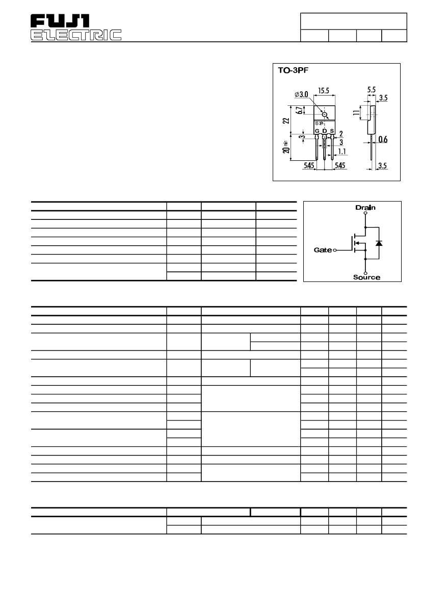
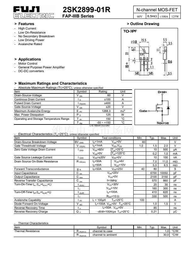
> Outline Drawing
> Applications
- Motor Control
- General Purpose Power Amplifier
- DC-DC converters
> Maximum Ratings and Characteristics
- Absolute Maximum Ratings (T
C
=25擄C),
unless otherwise specified
Item
Drain-Source-Voltage
Continous Drain Current
Pulsed Drain Current
Gate-Source-Voltage
Maximum Avalanche Energy
Max. Power Dissipation
Operating and Storage Temperature Range
Symbol
V
DS
I
D
I
D(puls)
V
GS
E
AV
P
D
T
ch
T
stg
Rating
60
鹵100
鹵400
鹵20
1268.3
125
150
-55 ~ +150
L=0.169mH,Vcc=24V
Unit
V
A
A
V
mJ*
W
擄C
擄C
- Electrical Characteristics (T
C
=25擄C),
unless otherwise specified
Item
Drain-Source Breakdown-Voltage
Gate Threshhold Voltage
Zero Gate Voltage Drain Current
Gate Source Leakage Current
Drain Source On-State Resistance
Forward Transconductance
Input Capacitance
Output Capacitance
Reverse Transfer Capacitance
Turn-On-Time t
on
(t
on
=t
d(on)
+t
r
)
Turn-Off-Time t
off
(t
on
=t
d(off)
+t
f
)
Avalanche Capability
Diode Forward On-Voltage
Reverse Recovery Time
Reverse Recovery Charge
Symbol
BV
DSS
V
GS(th)
I
DSS
I
R
g
C
C
C
t
t
t
t
I
V
t
Q
GSS
DS(on)
fs
iss
oss
rss
d(on)
r
d(off)
f
AV
SD
rr
rr
Test conditions
I
D
=1mA
V
GS
=0V
I
D
=1mA
V
DS=
V
GS
V
DS
=60V
T
ch
=25擄C
V
GS
=0V
T
ch
=125擄C
V
GS
=鹵20V
V
DS
=0V
I
D
=50A
V
GS
=4V
I
D
=50A
V
GS
=10V
I
D
=50A
V
DS
=25V
V
DS
=25V
V
GS
=0V
f=1MHz
V
CC
=30V
V
GS
=10V
I
D
=100A
R
GS
=10
鈩?/div>
T
ch
=25擄C
L = 100碌H
I
F
=100A V
GS
=0V T
ch
=25擄C
I
F
=50A V
GS
=0V
-dI/dt=100A/碌s T
ch
=25擄C
Min.
60
1,0
Typ.
1,5
10
0,2
10
7,0
5,0
80
6700
2100
570
20
160
410
330
1,0
85
0,21
Max.
2,0
500
1,0
100
11,0
6,5
10050
3150
860
30
300
620
500
1,5
40
100
Unit
V
V
碌A(chǔ)
mA
nA
m鈩?/div>
m鈩?/div>
S
pF
pF
pF
ns
ns
ns
ns
A
V
ns
碌C
- Thermal Characteristics
Item
Thermal Resistance
R
R
th(ch-c)
th(ch-a)
Symbol
channel to case
channel to ambient
Min.
Typ.
Max.
1,0
30,0
Unit
擄C/W
擄C/W


 1
1
 2
2
 3
3
