4鈩?/div>
3A
80W
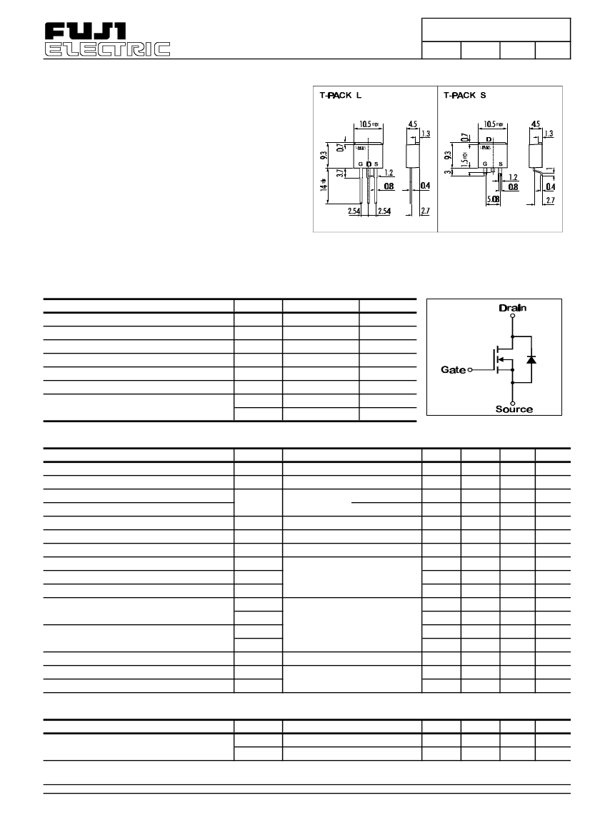
> Outline Drawing
> Applications
-
-
-
-
Switching Regulators
UPS
DC-DC Converters
General Purpose Power Amplifier
> Maximum Ratings and Characteristics
- Absolute Maximum Ratings (T
C
=25擄C),
unless otherwise specified
Item
Drain-Source-Voltage
Continous Drain Current
Pulsed Drain Current
Continous Reverse Drain Current
Gate-Source-Voltage
Max. Power Dissipation
Operating and Storage Temperature Range
Symbol
V
DS
I
D
I
D(puls)
I
DR
V
GS
P
D
T
ch
T
stg
Rating
800
3
12
3
鹵20
80
150
-55 ~ +150
Unit
V
A
A
A
V
W
擄C
擄C
> Equivalent Circuit
- Electrical Characteristics (T
C
=25擄C),
unless otherwise specified
Item
Drain-Source Breakdown-Voltage
Gate Threshhold Voltage
Zero Gate Voltage Drain Current
Gate Source Leakage Current
Drain Source On-State Resistance
Forward Transconductance
Input Capacitance
Output Capacitance
Reverse Transfer Capacitance
Turn-On-Time t
on
(t
on
=t
d(on)
+t
r
)
Turn-Off-Time t
off
(t
on
=t
d(off)
+t
f
)
Diode Forward On-Voltage
Reverse Recovery Time
Symbol
V
(BR)DSS
V
GS(th)
I
DSS
I
R
g
C
C
C
t
t
t
t
V
t
GSS
DS(on)
fs
iss
oss
rss
d(on)
r
d(off)
f
SD
rr
Test conditions
I
D
=1mA
V
GS
=0V
I
D
=10mA
V
DS=
V
GS
V
DS
=800V
T
ch
=25擄C
V
GS
=0V
T
ch
=125擄C
V
GS
=鹵20V
V
DS
=0V
I
D
=1,5A
V
GS
=10V
I
D
=1,5A
V
DS
=25V
V
DS
=25V
V
GS
=0V
f=1MHz
V
CC
=30V
I
D
=2,1A
V
GS
=10V
R
GS
=50鈩?/div>
I
F
=2xI
DR
V
GS
=0V T
ch
=25擄C
I
F
=I
DR
V
GS
=0V
-dI
F
/dt=100A/碌s T
ch
=25擄C
Min.
800
2,1
Typ.
3,0
0,01
0,2
10
3
4
900
90
35
20
40
150
60
1
400
Max.
4,0
0,5
1,0
100
4
1400
140
60
30
60
250
90
1,35
Unit
V
V
mA
mA
nA
鈩?/div>
S
pF
pF
pF
ns
ns
ns
ns
V
ns
2
- Thermal Characteristics
Item
Thermal Resistance
Symbol
R
th(ch-a)
R
th(ch-c)
Test conditions
channel to air
channel to case
Min.
Typ.
Max.
125
1,56
Unit
擄C/W
擄C/W
FUJI ELECTRIC GmbH; Lyoner Stra脽e 26; D-60528 Frankfurt; Tel: 069-66 90 29-0; Fax: 069-66 90 29-56


 1
1
 2
2
