Transistor
2SB0774
(2SB774)
Silicon PNP epitaxial planer type
For low-frequency amplification
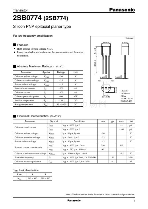
Unit: mm
5.0鹵0.2
4.0鹵0.2
I
Features
G
I
Absolute Maximum Ratings
Parameter
Collector to base voltage
Collector to emitter voltage
Emitter to base voltage
Peak collector current
Collector current
Collector power dissipation
Junction temperature
Storage temperature
Symbol
V
CBO
V
CEO
V
EBO
I
CP
I
C
P
C
T
j
T
stg
(Ta=25藲C)
Ratings
鈥?0
鈥?5
鈥?5
鈥?00
鈥?00
400
150
鈥?5 ~ +150
Unit
V
V
V
mA
mA
mW
藲C
藲C
13.5鹵0.5
5.1鹵0.2
G
High emitter to base voltage V
EBO
.
Protective diodes and resistances between emitter and base can
be omitted.
0.45
鈥?.1
1.27
+0.2
0.45
鈥?.1
1.27
+0.2
1 2 3
2.3鹵0.2
2.54鹵0.15
1:Emitter
2:Collector
3:Base
JEDEC:TO鈥?2
EIAJ:SC鈥?3A
I
Electrical Characteristics
Parameter
Collector cutoff current
Collector to base voltage
Collector to emitter voltage
Emitter to base voltage
Forward current transfer ratio
Collector to emitter saturation voltage
Transition frequency
Collector output capacitance
(Ta=25藲C)
Symbol
I
CBO
I
CEO
V
CBO
V
CEO
V
EBO
h
FE1*
h
FE2
V
CE(sat)
f
T
C
ob
Conditions
V
CB
= 鈥?0V, I
E
= 0
V
CE
= 鈥?0V, I
B
= 0
I
C
= 鈥?0碌A, I
E
= 0
I
C
= 鈥?mA, I
B
= 0
I
E
= 鈥?0碌A, I
C
= 0
V
CE
= 鈥?0V, I
C
= 鈥?mA
V
CE
= 鈥?V, I
C
= 鈥?00mA
I
C
= 鈥?00mA, I
B
= 鈥?0mA
V
CB
= 鈥?0V, I
E
= 2mA, f = 200MHz
V
CB
= 鈥?0V, I
E
= 0, f = 1MHz
150
4
鈥?0
鈥?5
鈥?5
210
90
鈥?.5
V
MHz
pF
460
min
typ
max
鈥?
鈥?00
Unit
碌A
碌A
V
V
V
*
h
FE1
Rank classification
R
210 ~ 340
S
290 ~ 460
Rank
h
FE1
Note.) The Part number in the Parenthesis shows conventional part number.
1


 1
1
 2
2
 3
3
