鈥?/div>
TO-126B package which requires no insulation plate for installa-
tion to the heat sink
蠁
3.16
鹵0.1
8.0
+0.5
鈥?.1
3.2
鹵0.2
3.8
鹵0.3
11.0
鹵0.5
1.9
鹵0.1
I
Absolute Maximum Ratings
T
C
=
25擄C
Parameter
Collector to base voltage
Collector to emitter voltage
Emitter to base voltage
Peak collector current
Collector current
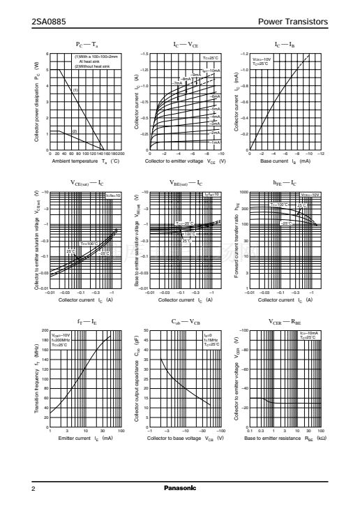
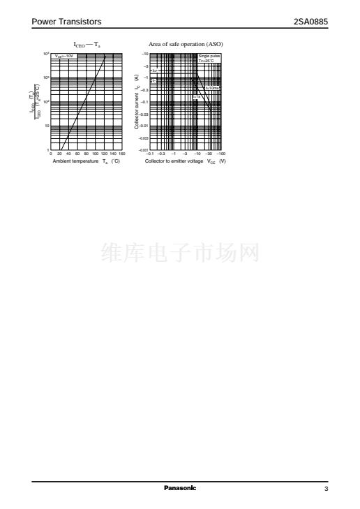
Collector power dissipation
Symbol
V
CBO
V
CEO
V
EBO
I
CP
I
C
P
C
T
j
T
stg
Rating
鈭?5
鈭?5
鈭?
鈭?.5
鈭?
1.2
*1
5
Junction temperature
Storage temperature
*2
0.75
鹵0.1
0.5
鹵0.1
0.5
鹵0.1
1.76
鹵0.1
2.3
鹵0.2
3
Unit
V
V
V
A
A
W
擄C
擄C
4.6
鹵0.2
16.0
鹵1.0
1
2
1: Emitter
2: Collector
3: Base
TO-126B Package
150
鈭?5
to
+150
Note) *1: Without heat sink
*2: With a 100
脳
100
脳
2 mm A1 heat sink
I
Electrical Characteristics
T
C
=
25擄C
Parameter
Collector cutoff current
Symbol
I
CBO
I
CEO
Emitter cutoff current
Collector to base voltage
Collector to emitter voltage
Forward current transfer ratio
I
EBO
V
CBO
V
CEO
h
FE1 *
h
FE2
Collector to emitter saturation voltage
Transition frequency
Collector output capacitance
Note) *: Rank classification
Rank
h
FE1
Q
85 to 170
R
120 to 240
S
170 to 340
V
CE(sat)
f
T
C
ob
Conditions
V
CB
=
鈭?0
V, I
E
= 0
V
CE
=
鈭?0
V, I
B
= 0
V
EB
=
鈭?V,
I
C
= 0
I
C
=
鈭?0 碌A(chǔ),
I
E
= 0
I
C
=
鈭?
mA, I
B
= 0
V
CE
=
鈭?0
V, I
C
=
鈭?00
mA
V
CE
=
鈭?
V, I
C
=
鈭?
A
I
C
=
鈭?00
mA, I
B
=
鈭?0
mA
V
CB
=
鈭?0
V, I
E
= 50 mA, f = 200 MHz
V
CB
=
鈭?0
V, I
E
= 0, f = 1 MHz
200
20
30
鈭?5
鈭?5
85
50
鈭?/div>
0.5
V
MHz
pF
340
Min
Typ
Max
鈭?/div>
0.1
鈭?00
鈭?0
Unit
碌A(chǔ)
碌A(chǔ)
碌A(chǔ)
V
V
Note.) The Part number in the Parenthesis shows conventional part number.
3.05
鹵0.1
1


 1
1
 2
2
 3
3
 4
4
