鈮?/div>
50
碌s)
Symbol
VDSS
VDGR
ID
ID
IDM
Value
60
60
鹵115
鹵75
鹵800
Unit
Vdc
Vdc
mAdc
http://onsemi.com
115 mAMPS
60 VOLTS
RDS(on) = 7.5
W
N鈥揅hannel
3
VGS
VGSM
鹵20
鹵40
Vdc
Vpk
1
THERMAL CHARACTERISTICS
Characteristic
Total Device Dissipation FR鈥? Board
(Note 3.) TA = 25擄C
Derate above 25擄C
Thermal Resistance, Junction to Ambient
Total Device Dissipation
Alumina Substrate,(Note 4.) TA = 25擄C
Derate above 25擄C
Thermal Resistance, Junction to Ambient
Junction and Storage Temperature
Symbol
PD
Max
225
1.8
556
300
2.4
R
胃JA
TJ, Tstg
417
鈥?5 to
+150
擄C/W
擄C
Unit
mW
mW/擄C
擄C/W
mW
mW/擄C
2
3
R
胃JA
PD
1
2
SOT鈥?3
CASE 318
STYLE 21
1. The Power Dissipation of the package may result in a lower continuous drain
current.
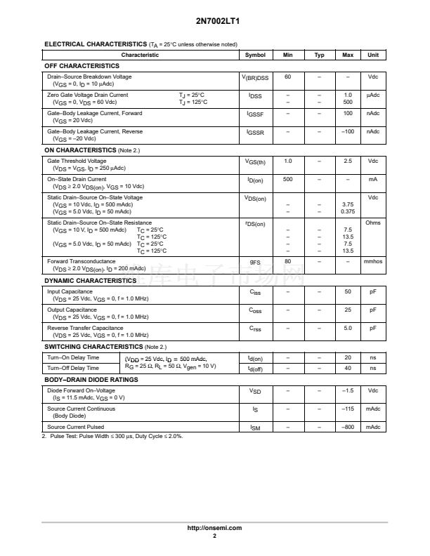
2. Pulse Test: Pulse Width
鈮?/div>
300
碌s,
Duty Cycle
鈮?/div>
2.0%.
3. FR鈥? = 1.0 x 0.75 x 0.062 in.
4. Alumina = 0.4 x 0.3 x 0.025 in 99.5% alumina.
MARKING DIAGRAM
& PIN ASSIGNMENT
Drain
3
702
W
1
2
Gate
702
W
Source
= Device Code
= Work Week
ORDERING INFORMATION
Device
2N7002LT1
2N7002LT3
Package
SOT鈥?3
SOT鈥?3
Shipping
3000 Tape & Reel
10,000 Tape & Reel
Preferred
devices are recommended choices for future use
and best overall value.
漏
Semiconductor Components Industries, LLC, 2000
1
December, 2000 鈥?Rev. 4
Publication Order Number:
2N7002LT1/D


 1
1
 2
2
 3
3
 4
4
 5
5
 6
6
 7
7
 8
8
