(a)
Beschreibung
(a)
Description
SPECIALISTS IN MACHINERY SAFETY
Minotaur
MSR7R
2 HAND CONTROL LOGIC UNIT
2-HAND-SICHERHEITSBAUSTEIN
BLOC LOGIQUE DE CONTR脭LE BIMANUEL
See enclosed Declaration of Conformity for details.
Siehe Anlage: Konformit盲tserkl盲rung.
Voir la declaration de conformite ci-jointe pour details.
(b)
Installation
The Minotaur MSR7R is a safety relay
specifically designed for monitoring of two
hand control switches. Using dual channel
inputs, the unit checks the operation of
two independent 1 N/O and 1 N/C
actuators and then gives the approprite
output signal. If the two input signals
conflict for more than 0.5 seconds, the
MSR7R locks out, isolating control power
to the machine contactor. The unit also has
a contactor monitoring loop. If these
terminals are connected to positively
guided N/C auxiliary contacts on the
machine contactor, the unit will detect if
any one contactor fails to isolate the power
at de-energisation of its control coil by
locking out the unit.
Der Minotaur MSR7R ist ein
Sicherheitsbaustein, der speziell f眉r
脺berwachung von Zwei-Hand-Tastern
entwickelt wurde. Mit einer 2-kanaligen
Eingangskonfiguration 眉berwacht das
Ger盲t zwei unabh盲ngige Stromkreise mit
je 1脰 und 1S und liefert dann die
entsprechenden Ausgangssignale. Falls die
beiden Eingangssignale l盲nger als 0,5 s
nicht 眉bereinstimmen, schaltet der MSR7R
ab und unterbricht die Stromversorgung zu
den Maschinensch眉tzen. Das Ger盲t ist auch
mit Eing盲ngen f眉r die Sch眉tz眉berwachung
versehen. Falls diese Klemmen mit den 脰
ffner-Hilfskontakten des Sch眉tzes
verbunden werden, entdeckt das Ger盲t,
wenn eines der Sch眉tze bei Deaktivierung
seiner Spule nicht abschaltet, und schaltet
den Sicherheitskreis ab.
(a)
Description
Le Minotaur MSR7R est un relais de
s茅curit茅 sp茅cialement con莽u pour la
surveillance des deux mains. Utilisant
deux canaux d'entr茅e, il contr么le
l'enclenchement de deux canaux
ind茅pendants 1N/O & 1N/C et fournit les
sorties de s茅curit茅 appropri茅es. Si les deux
signaux d'entr茅e sont en conflit plus de
0.5 secondes, le MSR7R se bloque, coupant
l'alimentation des contacteurs de la
machine. L'unit茅 poss貓de aussi une boucle
de retour pour le contr么le de collage des
contacteurs. Si ces bornes sont connrct茅es
aux contacts auxiliaires N/C des
contacteurs de la machine, l'unit茅
d茅tectera si l'un des contacteurs n'est pas
bloqu茅 脿 l'appel.
Instructions
Einbauanleitung
DIESE ANLEITUNG AUFBEWAHREN
Die Montage ist entsprechend den folgenden Sc hritten durchzuf眉hren.
ANMERKUNG:
Falls das Ger盲t f眉r Sicherheitsaufgaben eingesetzt
werden soll, mu脽 die Tastereinheit den Anforderungen
von EN 574 entsprechen.
Notice D'installation
GARDEZ EN MEMOIRE CES INSTRUCTIONS
L'installation dev ra suivre les 茅tapes suivantes et sera
effectu茅e par du personnel comp茅t ent et qualifi茅.
NOTE:
Si le syst貓me est utilis茅 dans un but de s茅curit茅,
les boutons doivent 錨tre conformes aux
exigences se la norme en 574
(c)
RETAIN THESE INSTRUCTIONS
Installation must be in accordance with the following steps
and must be carried out by suitably competent personnel.
(d)
NOTE:
If the system is to be used for safety related
purposes, the switch buttons unit should comply with the
requiremnts of EN 574.
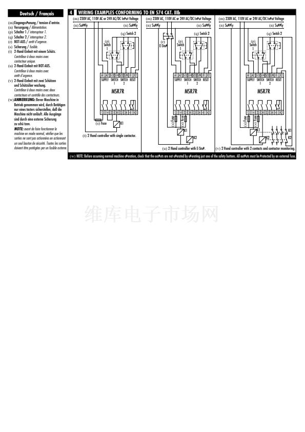
Deutsch / Fran莽ais
1
(e)
Back View
2
(e)
R眉ckansicht /
Vue arri貓re.
(f)
Auf 35mm-Normschiene.
Montage sur rail DIN 35mm.
(g)
In Geh盲use mit mind. IP 54 anbringen.
A monter dans coffret minimum IP 54.
(h)
Anschl眉sse:
A1 & A2 = Versorgung 230 oder 110V AC
oder 24V AC/DC. (siehe Ger盲teseite)
S13 = Schlie脽er Schalter 1.
S24 = Schlie脽er Schalter 2.
S14 = 脰ffner Schalter 2- EN 574 Cat IIIb
S23 = 脰ffner Schalter 1- EN 574 Cat IIIb
(f)
Mount on 35mm DIN rail.
X2 = Sch眉tz眉berwachung.
X1 = Gemeinsamer Pol (siehe Schritt 4).
(g)
Mount in enclosure
41 x 42 = Hilfsausgang (脰).
to a min of IP 54.
13 x 14 = Sicherheitsaugang 1 (S).
23 x 24 = Sicherheitsaugang 2 (S).
33 x 34 = Sicherheitsaugang 3 (S).
Connexions:
A1 & A2 = alimentation 230 ou 110V AC ou
(j)
Vor Abnehmen des Deckels
24V AC/DC (voir ci-contre pour
Spannung abschalten.
plus de d茅tails)
Isoler les alimentations.
S13 = entr茅e circuit 1 (N/O)
(k)
Austauschen Sicherung.
S24 = entr茅e circuit 2 (N/O)
Fusible rempla莽able.
S14 = entr茅e circuit 2 - EN 574 Cat IIIb (N/C)
S23 = entr茅e circuit 1 - EN 574 Cat IIIb (N/C)
X2 = contr么le de sortie (contacteur)
X1 = commum (voir plan 4)
41 x 42 = sortie auxiliaire (N/C)
13 x 14 = sortie de s茅curit茅 1 (N/O)
23 x 24 = sortie de s茅curit茅 2 (N/O)
33 x 34 = sortie de s茅curit茅 3 (N/O)
(i)
LED Anzeigen:
POWER (ROT)
- Leuchtet, wenn
Spannung anliegt.
K1 (GR脺N)
- Leuchtet, wennn interner
Kontakt K1.
K2 (GR脺N)
- Leuchtet, wenn interner
Kontakt K2 geschlossen.
Indication LED:
ALIMENTATION (ROUGE)
- illumin茅e quand
l'unit茅 est sous tension.
K1 (VERT)
- illumin茅 quand les contacts
internes de K1 sont ferm茅s.
K2 (VERT)
- illumin茅 quand les contacts
internes de K2 sont ferm茅s.
X2 = Outputs (contactor) monitoring.
X1 = Common (see step 4).
A1 & A2 = Supply 230 or 110V AC
41 x 42 = Auxiliary output (N/C).
or 24V AC/DC.
(see side for details)
13 x 14 = Safety output 1 (N/O).
S13 = N/O from switch 1.
23 x 24 = Safety output 2 (N/O).
S24 = N/O from switch 2.
33 x 34 = Safety output 3 (N/O).
S14 = N/C (from switch 2- EN 574 Cat IIIb).
S23 = N/C (from switch 1- EN 574 Cat IIIb).
(h)
Connections
3
(j)
Isolate power before removing cover
A1 S13 S24 X1 41 13 23 33
(i)
LED Indication
POWER
(RED) - Illuminated when
there is power to the unit.
K1 (GREEN)
- Illuminated when
internal contacts K1 are closed.
500 mAT
(k)
Fuse replacement
A2 S14 S23 X2 42 14 24 34
K2 (GREEN)
- Illuminated when
internal contacts K2 are closed.


 1
1
 2
2
 3
3
 4
4
