脡lan
TM
SC300 and 脡lanSC310 Microcontrollers
GATEA20 Function Clarification
Application Note
This application note addresses several solutions for booting in systems that do not have external
control of the A20GATE pin in 脡lan
TM
SC300 and 脡lanSC310 microcontrollers.
GATEA20 FUNCTIONALITY
In 脡lan
T M
SC300 and 脡lanSC310 designs, the
GATEA20 functionality is achieved through pin 79
(A20GATE), Index 6Fh bit 0 (GATEA20), and Port 92h
bit 1 (ALTA20). Additionally, Index 6Bh bit 0 (A20SMI)
controls the GATEA20 function while the CPU is in the
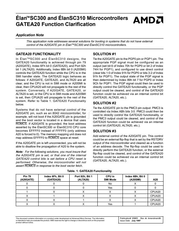
SMI handler state. The GATEA20 logic behaves as
follows: if A20GATE, GATEA20, and ALTA20 are all
clear, and the CPU is not in SMI mode or A20SMI is
clear, then CPUA20 will not propagate to the rest of the
system. Conversely, if A20GATE, GATEA20, or
ALTA20 is set, or the CPU is in SMI mode and A20SMI
is set, then CPUA20 will propagate to the rest of the
system. Refer to Table 1. GATEA20 Functionality
below.
Systems that do not have external control of the
A20GATE pin, such as an 8042 microcontroller, for
example, will not boot if the A20GATE pin is grounded
and the boot vector is located in a device that uses
ROMCS. If A20GATE is grounded, the boot address
asserted by the 脡lanSC300 or 脡lanSC310 CPU core
becomes EFFFF0 instead of FFFFF0 (only address
A20 is forced to 0). The memory mapping unit does not
map address EFFFF0 to ROMCS space at reset.
If the A20GATE pin is left unconnected, you will not be
able to disallow the propagation of A20 to the system.
SOLUTION #1
Tie the A20GATE pin to the PGP0 pin or PGP1 pin. The
appropriate PGP signal must be configured as an
output (set bit 6 of Index 70h for PGP0 or bit 2 of Index
74H for PGP1), and configured to use direct control
(clear bits 1:0 of Index 91h for PGP0 or bits 3:2 of Index
91h for PGP1). The output state of the PGP signal is
then determined by Index 89h bit 7 for PGP0 or Index
9Ch for PGP1. The PGP signal could then be used to
directly control the GATEA20 functionality, or the PGP
output could be cleared, and control of the GATEA20
function could be achieved via an internal control bit
(GATEA20, ALTA20, etc.).
SOLUTION #2
Tie the A20GATE pin to the PMC3 pin output. PMC3 is
controlled via Index ABh bits 3:0. PMC3 could then be
used to directly control the GATEA20 functionality, or
the PMC3 output could be cleared, and control of the
GATEA20 function could be achieved via an internal
control bit (GATEA20, ALTA20, etc.).
SOLUTION #3
Add external control of the A20GATE pin. This control
could be an external flip-flop that is set by the RSTDRV
output of the microcontroller and cleared as a function
of an address decode. The flip-flop could be used to
directly perform the GATEA20 function, or the external
flip-flop could be cleared, and control of the GATEA20
function could be achieved via an internal control bit
(GATEA20, ALTA20, etc.).
Note:
For the following solutions, you must insure that
the A20GATE pin is set, or that one of the internal
GATEA20 control bits is set before a CPU reset is
performed. Otherwise, the microcontroller will not
assert ROMCS in response to the boot vector fetch.
Table. 1. GATEA20 Functionality
Pin 79
(A20GATE)
0
0
1
X
X
X
Index 6Fh, Bit 0
(GATEA20)
0
0
X
1
X
X
Port 92h, Bit 1
(ALTA20)
0
0
X
X
1
X
CPU in
SMI Mode
No
Yes
X
X
X
Yes
Index 6Bh, Bit 0
(A20SMI)
X
0
X
X
X
1
A20
0
0
CPUA20
CPUA20
CPUA20
CPUA20
This document contains information on a product under development at Advanced Micro Devices. The information
is intended to help you evaluate this product. AMD reserves the right to change or discontinue work on this proposed
product without notice.
Publication#
21811
Rev:
A
Amendment/0
Issue Date:
July 1997


 1
1
 2
2
