Designing 100BASE-TX Systems with the QFEX Family
Application Note
This application note provides a design reference for customers wishing to implement 100BASE-
TX systems, using QFEXr鈩?for the PHY hardware. An overview of QFEXr is included, but for further
detailed information, refer to the individual QFEXr data sheets. Although system design details such
as interfacing QFEXr to repeaters and proper board design and layout with QFEXr are provided,
only a few general high-speed design and general layout rules are addressed. Other sources of in-
formation for PHY layout and high-speed designs are listed in the References section.
INTRODUCTION
In response to the need for higher bandwidth than that
provided by 10BASE-T, the IEEE committee de鏗乶ed a
100-Mbps standard (100BASE-X), borrowing PHY
technology from the existing FDDI standard. This 100-
Mbps standard, also known as Fast Ethernet, offered
a 1 0 - t i m e s gr e a t e r s p e e d u s i n g t w i s t e d p a i r
(100BASE-TX) and 鏗乥er (100BASE-FX) for almost
equivalent cost to 10BASE-T.
100BASE-TX de鏗乶es transmission of data over UTP
Category 5 cable and de鏗乶es layers of functionality
implemented to support 100-Mbps communication. A
layer of particular interest is the physical (PHY) layer
which de鏗乶es the technology required to convert line
signals into frames of data that other layers beyond
the PHY layer can use. The PHY layer connects to
hardware such as network cards, switches, and re-
peaters. This application note will focus on repeaters
and PHY connectivity.
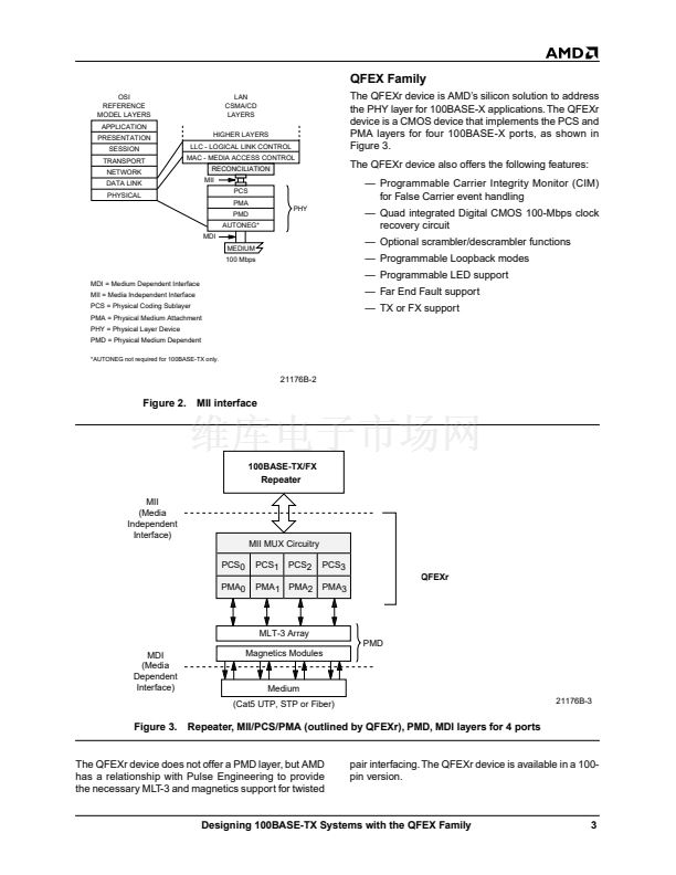
AMD recently introduced the 鏗乺st member of its PHY
family, the QFEXr device. The QFEXr device is a four-
port physical layer device used for 100BASE-X re-
peater applications.
100BASE-TX repeater designs can provide bene鏗乼s of
higher data bandwidth for signi鏗乧antly less than 10
times cost.
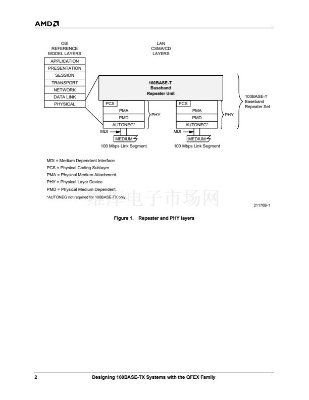
As shown in Figure 1, a repeater and a PHY layer are
needed to realize a 100BASE-TX repeater design.
Figure 1 shows the components of a 100BASE-T re-
peater. Note that the repeater is part of the Physical
layer of the OSI model. To convert this into a 100BASE-
TX system, the Medium and Medium Dependent Inter-
face (MDI)become a twisted pair interface.
The PHY is comprised of three to four sublayers: the
Physical Coding Sublayer (PCS), Physical Medium At-
tachment (PMA), Physical Medium Dependent (PMD),
and, optionally, the Auto-Negotiation sublayer.
Note:
The Auto-Negotiation sublayer is not required in
the 100 Mbps-only repeater designs.
Although the PHY can seamlessly attach to the re-
peater, as shown in Figure 1, this is not the case with
current market implementations, where only separate
PHY and repeater devices are available. Therefore, an
interface is required to connect the PHY to the re-
peater, and the most commonly used interface is the
Medium Independent Interface (MII). The MII is also
de鏗乶ed by the 100BASE-X standard and provides a
level of compatibility between all silicon solutions today.
An MII interface and its relation to the PHY is shown in
Figure 2.
Using the MII allows an easy connection of any re-
peater with the MII interface to any PHY or other silicon
device that also has an MII interface.
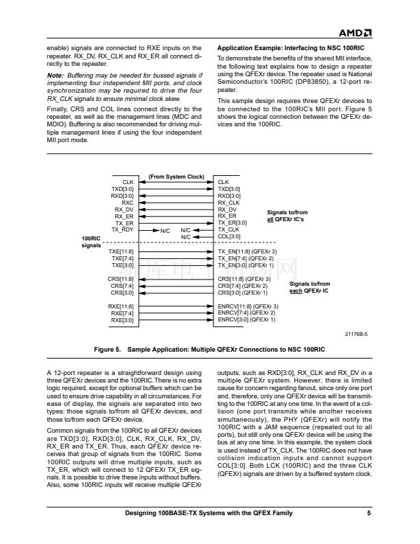
100BASE-TX REPEATERS
Designing 100BASE-TX repeaters is similar to design-
ing 10BASE-T repeaters over the same twisted pair in-
terface. The differences in designing 100BASE-TX vs.
10BASE-T repeaters are a 10 times jump in data rates
from 10 Mbps to 100 Mbps, the method of data decod-
ing/encoding, and the availability of a Signal Detect
function for link integrity. These features make
100BASE-TX more intricate than 10BASE-T, but
This document contains information on a product under development at Advanced Micro Devices. The information
is intended to help you evaluate this product. AMD reserves the right to change or discontinue work on this proposed
product without notice.
Publication#
21176
Rev:
B
Amendment/0
Issue Date:
July 1997


 1
1
 2
2
 3
3
 4
4
 5
5
 6
6
 7
7
 8
8
 9
9
 10
10
 11
11
 12
12
 13
13
 14
14
 15
15
