Fiber Optic Receiver
Recommended Operating Conditions
Parameter
Symbol
V
cc
Operating supply voltage
Operating transfer rate
T
receiver input optical power level
Pc
MOF-R3K2
MIN.
4.75
0.1
-22
TYP.
5.0
---
---
MAX.
5.25
6
-14.5
Unit
V
Mbps
dBm
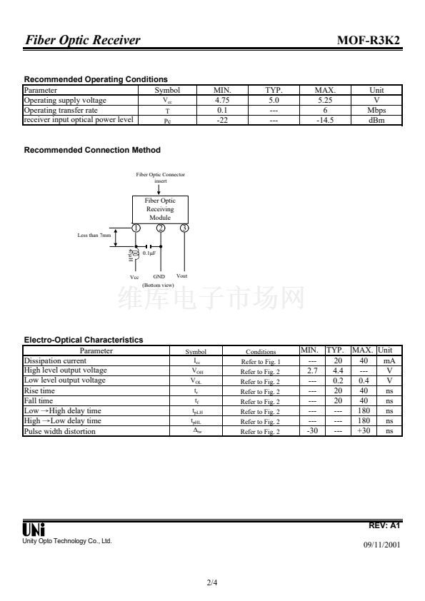
Recommended Connection Method
Fiber Optic Connector
insert
Fiber Optic
Receiving
Module
1
Less than 7mm
47碌H
Vcc
0.1碌F
2
3
GND
(Bottom view)
Vout
Electro-Optical Characteristics
Parameter
Dissipation current
High level output voltage
Low level output voltage
Rise time
Fall time
Low
鈫扝igh
delay time
High
鈫扡ow
delay time
Pulse width distortion
Symbol
I
cc
V
OH
V
OL
t
r
t
f
t
pLH
t
pHL
鈭?/div>
tw
Conditions
Refer to Fig. 1
Refer to Fig. 2
Refer to Fig. 2
Refer to Fig. 2
Refer to Fig. 2
Refer to Fig. 2
Refer to Fig. 2
Refer to Fig. 2
MIN. TYP.
---
20
2.7
4.4
---
0.2
---
20
---
20
---
---
---
---
-30
---
MAX. Unit
40
mA
---
V
0.4
V
40
ns
40
ns
180
ns
180
ns
+30
ns
REV: A1
Unity Opto Technology Co., Ltd.
09/11/2001
2/4


 1
1
 2
2
 3
3
 4
4
