MITSUMI
RGB Video Amplifier for Monitors MM1203
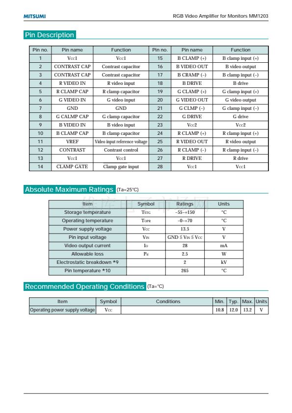
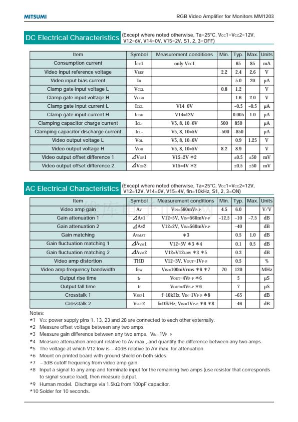
DC Electrical Characteristics
Item
Consumption current
Video input reference voltage
Video input bias current
Clamp gate input voltage L
Clamp gate input voltage H
Clamp gate input current L
Clamp gate input current H
Clamping capacitor charge current
Clamping capacitor discharge current
Video output voltage L
Video output voltage H
Video output offset difference 1
Video output offset difference 2
(Except where noted otherwise, Ta=25擄C, V
CC
1=V
CC
2=12V,
V12=6V, V14=0V, V15=2V, S1, 2, 3=OFF)
Symbol
I
CC
1
V
REF
I
B
V
CGL
V
CGH
I
CGL
I
CGH
I
CL+
I
CL-
V
OL
V
OH
V
OF
1
V
OF
2
V14=0V
V14=12V
V5, 8, 10=0V
V5, 8, 10=5V
V5, 8, 10=0V
V5, 8, 10=5V
V15=2V
8.2
500
0.8
Measurement conditions
only V
CC
1
2.2
Min. Typ. Max. Units
65
2.4
5.0
1.2
1.6
-0.5
0.005
850
0.9
8.9
鹵0.5
鹵0.5
鹵50
鹵50
1.25
-500 -850
2.0
-0.5
1.0
85
2.6
20
mA
V
碌A(chǔ)
V
V
碌A(chǔ)
碌A(chǔ)
碌A(chǔ)
碌A(chǔ)
V
V
mV
mV
*
2
V15=4V 2
*
AC Electrical Characteristics
Item
Video amp gain
Gain attenuation 1
Gain attenuation 2
Gain matching
Gain fluctuation matching 1
Gain fluctuation matching 2
Video amp distortion
Video amp frequency bandwidth
Output rise time
Output fall time
Crosstalk 1
Crosstalk 2
(Except where noted otherwise, Ta=25擄C, V
CC
1=V
CC
2=12V,
V12=12V, V14=0V, V15=4V, fin=10kHz, S1, 2, 3=ON)
Symbol
A
V
A
V
1
A
V
2
A
VMAT
A
VM
1
A
VM
2
THD
f
BW
t
r
t
f
V
SEP
1
V
SEP
2
Measurement conditions
V
IN
=560mV
P-P
V12=5V, V
IN
=560mV
P-P
V12=2V, V
IN
=560mV
P-P
Min. Typ. Max. Units
4.5
-12.5
6.0
-10
-40
0.5
0.1
0.3
0.5
70
120
5
7
-65
-46
1.0
0.5
-7.5
V/V
dB
dB
dB
dB
dB
%
MHz
碌S
碌S
dB
dB
*
3
V12=5V 3 4
* *
V12=V12
*
3
*
5
LOW
V12=3V, V
OUT
=1V
P-P
*
6
*
7
V =4V
*
6
V =4V
*
6
f=10kHz, V =1V
*
8
f=10kHz, V =1V
*
6
*
8
OUT
OUT
P-P
P-P
IN
P-P
IN
P-P
V
IN
=100mVrms
Notes:
1 V
CC
power supply pins 1, 13, 23 and 28 are connected to each other externally.
2 Measure offset voltage between any two amps.
3 Measure gain difference between any two amps. V
IN
=1V
P-P
4 Measure attenuation amount relative to Av max., and quantify the difference between any two amps.
5 The voltage at which V12 low is -40dB relative to AV max. for attenuation.
6 Mount on printed board with ground shield on both sides.
7 -3dB cutoff frequency from video amp gain.
8 Input a signal to any amp and terminate input for the remaining two amps (use resistor that corresponds
to signal source load), then measure output.
9 Human model. Discharge via 1.5k鈩?from 100pF capacitor.
10 Solder for 10 seconds.
*
*
*
*
*
*
*
*
*
*


 1
1
 2
2
 3
3
 4
4
 5
5
 6
6
