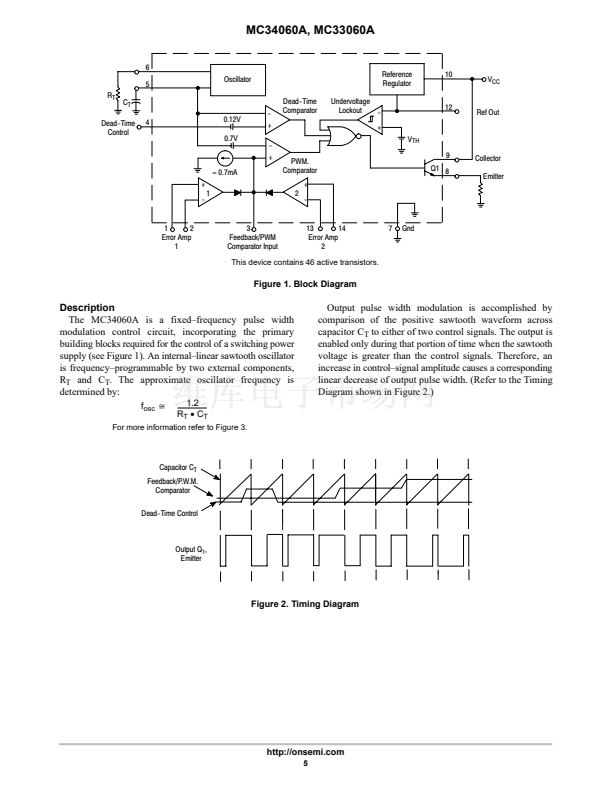
MC34060A, MC33060A
VTH , UNDERVOLTAGE LOCKOUT THRESHOLD (V)
10
9.0
I CC, SUPPLY CURRENT (mA)
8.0
7.0
6.0
5.0
4.0
3.0
2.0
1.0
0
0
5.0
10
15
20
25
30
35
40
6.0
5.5
Turn On
5.0
4.5
Turn Off
4.0
0
5.0
10
15
20
25
30
35
40
V
CC
, SUPPLY VOLTAGE (V)
I
L
, REFERENCE LOAD CURRENT (mA)
Figure 9. Standby Supply Current
versus Supply Voltage
Figure 10. Undervoltage Lockout Thresholds
versus Reference Load Current
V
CC
= 15V
Dead-
Time
V
CC
150鈩?/div>
2W
C
E
Output
+
V
in
-
Error Amplifier
Under Test
Test
Inputs
Feedback
Terminal
(Pin 3)
+
V
ref
-
Other Error
Amplifier
50k鈩?/div>
Feedback
R
T
C
T
(+)
(-)
Error
(+)
(-)
Gnd
Ref
Out
Figure 11. Error Amplifier Characteristics
Figure 12. Deadtime and Feedback Control
15V
R
L
68鈩?/div>
C
Output
Transistor
E
C
L
15pF
V
C
Output
Transistor
E
R
L
68鈩?/div>
C
15V
V
E
C
L
15pF
90%
V
C
10%
t
r
90%
10%
t
f
90%
10%
t
r
t
f
90%
V
E
10%
Figure 13. Common鈥揈mitter Configuration
and Waveform
Figure 14. Emitter鈥揊ollower Configuration
and Waveform
http://onsemi.com
8


 1
1
 2
2
 3
3
 4
4
 5
5
 6
6
 7
7
 8
8
 9
9
 10
10
 11
11
 12
12
 13
13
 14
14
 15
15
 16
16
