ADM823/ADM824/ADM825
PIN CONFIGURATIONS AND FUNCTION DESCRIPTIONS
RESET
1
5
Preliminary Technical Data
V
CC
RESET
1
5
V
CC
RESET
1
5
V
CC
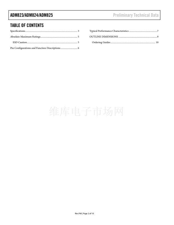
ADM823
GND
2
MR
3
04534-0-002
ADM824
GND
2
4
04534-0-003
ADM825
GND
2
4
04534-0-004
TOP VIEW
(Not to Scale)
WDI
TOP VIEW
(Not to Scale)
WDI
TOP VIEW
(Not to Scale)
4
RESET
3
RESET
3
MR
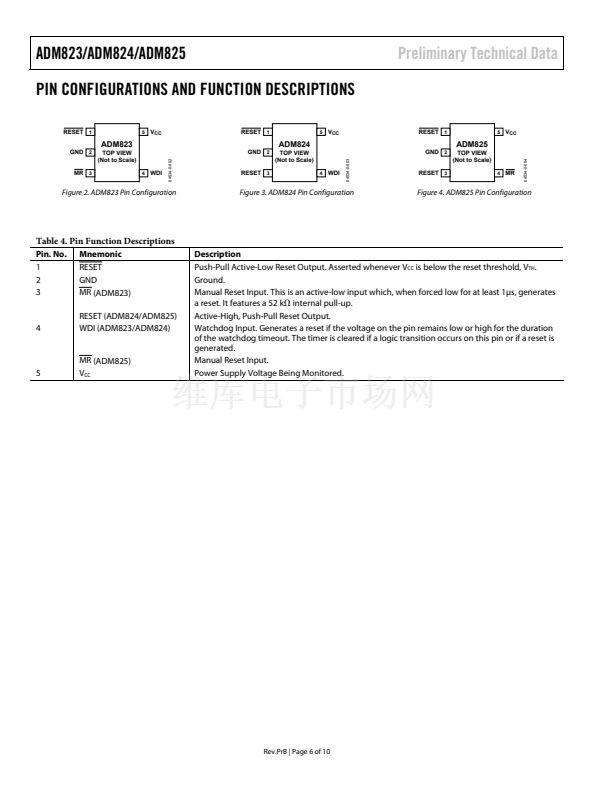
Figure 2. ADM823 Pin Configuration
Figure 3. ADM824 Pin Configuration
Figure 4. ADM825 Pin Configuration
Table 4. Pin Function Descriptions
Pin. No.
1
2
3
Mnemonic
RESET
GND
MR (ADM823)
RESET (ADM824/ADM825)
WDI (ADM823/ADM824)
Description
Push-Pull Active-Low Reset Output. Asserted whenever V
CC
is below the reset threshold, V
TH
.
Ground.
Manual Reset Input. This is an active-low input which, when forced low for at least 1碌s, generates
a reset. It features a 52 k internal pull-up.
Active-High, Push-Pull Reset Output.
Watchdog Input. Generates a reset if the voltage on the pin remains low or high for the duration
of the watchdog timeout. The timer is cleared if a logic transition occurs on this pin or if a reset is
generated.
Manual Reset Input.
Power Supply Voltage Being Monitored.
4
5
MR (ADM825)
V
CC
Rev.PrB | Page 6 of 10


 1
1
 2
2
 3
3
 4
4
 5
5
 6
6
 7
7
 8
8
 9
9
 10
10
