SLUS593B 鈭?DECEMBER 2003 鈭?REVISED APRIL 2004
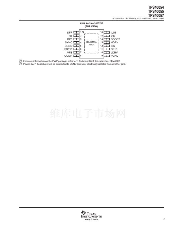
TPS40054
TPS40055
TPS40057
APPLICATION INFORMATION
The minimum current limit setpoint (I
LIM
) depends on t
START
, C
O
, V
O
, and the load current at turn-on (I
L
).
I
LIM
+
C
O
V
O
t
START
)
I
L
(Amperes)
(15)
HDRV
CLOCK
tBLANKING
VILIM
VVIN鈭扸SW
SS
7 CURRENT LIMIT TRIPS
(HDRV CYCLE TERMINATED BY CURRENT LIMIT
TRIP)
7 SOFT-START CYCLES
UDG鈭?2136
Figure 9. Typical Current Limit Protection Waveforms
The current limit programming resistor (R
ILIM
) is calculated using equation (16).
R
ILIM
+
where:
I
OC
R
DS(on)[max]
I
SINK
1.12
)
V
OS
I
SINK
(W)
(16)
D
I
SINK
is the current into the ILIM pin and is nominally 10
碌A,
D
I
OC
is the overcurrent setpoint which is the DC output current plus one-half of the peak inductor current
D
V
OS
is the overcurrent comparator offset and
is nominally 鈭?5 mV
SYNCHRONIZING TO AN EXTERNAL SUPPLY
The TPS4005x can be synchronized to an external clock through the SYNC pin. Synchronization occurs on the
falling edge of the SYNC signal. The synchronization frequency should be in the range of 20% to 30% higher
than its programmed free-run frequency. The clock frequency at the SYNC pin replaces the master clock
generated by the oscillator circuit. Pulling the SYNC pin low programs the TPS4005x to freely run at the
frequency programmed by R
T
.
16
www.ti.com


 1
1
 2
2
 3
3
 4
4
 5
5
 6
6
 7
7
 8
8
 9
9
 10
10
 11
11
 12
12
 13
13
 14
14
 15
15
 16
16
 17
17
 18
18
 19
19
 20
20
 21
21
 22
22
 23
23
 24
24
 25
25
 26
26
 27
27
 28
28
 29
29
 30
30
 31
31
 32
32
 33
33
