TPS40007
TPS40009
SLUS589A鈭?NOVEMBER 2003 鈭?REVISED MAY 2004
APPLICATION INFORMATION
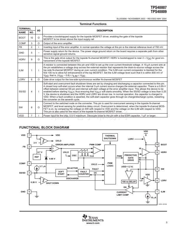
Detailed Description
During each switching cycle, a comparator looks at the voltage across the top side MOSFET while it is on. This
comparator is enabled after the SW node reaches a voltage greater than (V
DD
鈭?.2 V) followed by a 100-ns
blanking time. If the voltage across that MOSFET exceeds the programmed voltage, the current-switching pulse
is terminated and a 3-bit counter is incremented by one count. If, during the switching cycle, the topside
MOSFET voltage does not exceed a preset threshold, then this counter is decremented by one count. (The
counter does not wrap around from 7 to 0 or from 0 to 7). If the counter reaches a full count of 7, the device
declares that a fault condition exists at the output of the converter. In this fault state, HDRV and LDRV are turned
off, and the soft-start capacitor is discharged. LDRV is maintained OFF during fault timeout to effectively support
pre-bias applications. The counter is decremented by one by the soft start capacitor (C
SS
) discharge. When the
soft-start capacitor is fully discharged, the discharging circuit is turned off and the capacitor is allowed to charge
up at the nominal charging rate. When the soft-start capacitor reaches approximately 1.3 V, it is discharged
again and the overcurrent counter is decremented by one count. The capacitor is charged and discharged, and
the counter decremented until the count reaches zero (a total of six times). When this happens, the outputs are
again enabled as the soft-start capacitor generates a reference ramp for the converter to follow while attempting
to restart.
During this soft-start interval (whether or not the controller is attempting to do a fault recovery or starting for the
first time), pulse-by-pulse current limiting is in effect, but overcurrent pulses are not counted to declare a fault
until the soft-start cycle has been completed. It is possible to have a supply attempt to bring up a short circuit
for the duration of the soft start period plus seven switching cycles. Power stage designs should take this into
account if it makes a difference thermally. Figure 3 shows the details of the overcurrent operation.
(+)
VTS
(鈭?
Internal PWM
Short Circuit Protection
Threshold Voltage
VTS
0V
External
Main Drive
Normal
Cycle
Overcurrent
Cycle
UDG鈭?3165
Figure 3. Short Circuit Operation
www.ti.com
9


 1
1
 2
2
 3
3
 4
4
 5
5
 6
6
 7
7
 8
8
 9
9
 10
10
 11
11
 12
12
 13
13
 14
14
 15
15
 16
16
 17
17
 18
18
 19
19
 20
20
 21
21
 22
22
 23
23
