Philips Semiconductors
Product speci鏗乧ation
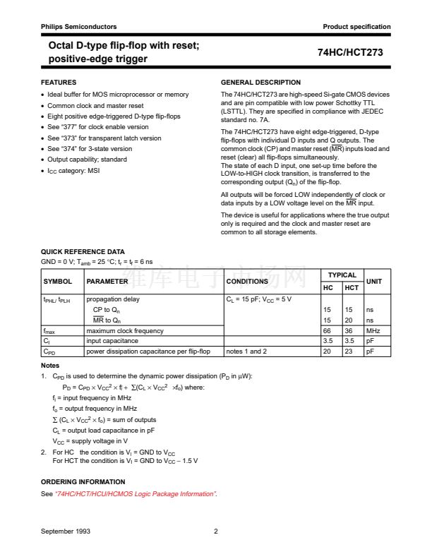
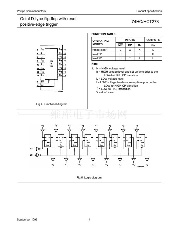
Octal D-type 鏗俰p-鏗俹p with reset;
positive-edge trigger
DC CHARACTERISTICS FOR 74HCT
For the DC characteristics see
鈥?4HC/HCT/HCU/HCMOS Logic Family Specifications鈥?
Output capability: standard
I
CC
category: MSI
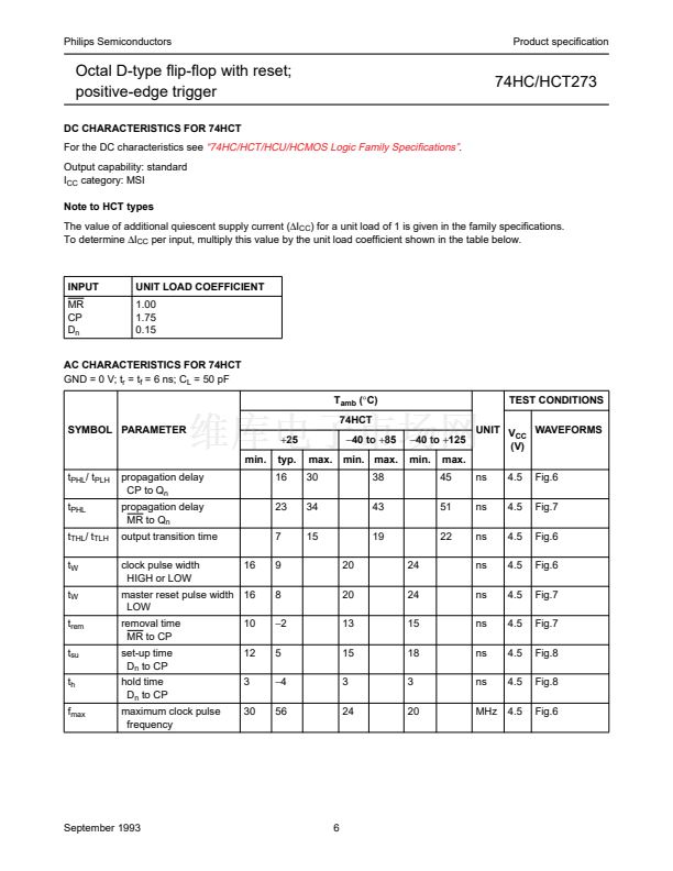
Note to HCT types
74HC/HCT273
The value of additional quiescent supply current (鈭咺
CC
) for a unit load of 1 is given in the family specifications.
To determine
鈭咺
CC
per input, multiply this value by the unit load coefficient shown in the table below.
INPUT
MR
CP
D
n
UNIT LOAD COEFFICIENT
1.00
1.75
0.15
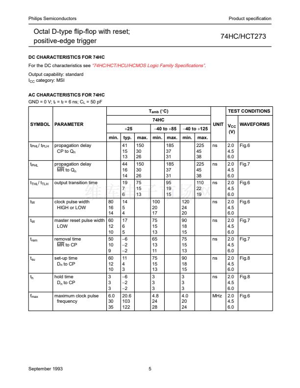
AC CHARACTERISTICS FOR 74HCT
GND = 0 V; t
r
= t
f
= 6 ns; C
L
= 50 pF
T
amb
(擄C)
74HCT
SYMBOL PARAMETER
min.
t
PHL
/ t
PLH
t
PHL
t
THL
/ t
TLH
t
W
t
W
t
rem
t
su
t
h
f
max
propagation delay
CP to Q
n
propagation delay
MR to Q
n
output transition time
clock pulse width
HIGH or LOW
16
+25
typ.
16
23
7
9
8
鈭?
5
鈭?
56
max.
30
34
15
20
20
13
15
3
24
鈭?0
to
+85
min. max.
38
43
19
24
24
15
18
3
20
UNIT V
WAVEFORMS
CC
鈭?0
to
+125
(V)
min. max.
45
51
22
ns
ns
ns
ns
ns
ns
ns
ns
MHz
4.5
4.5
4.5
4.5
4.5
4.5
4.5
4.5
4.5
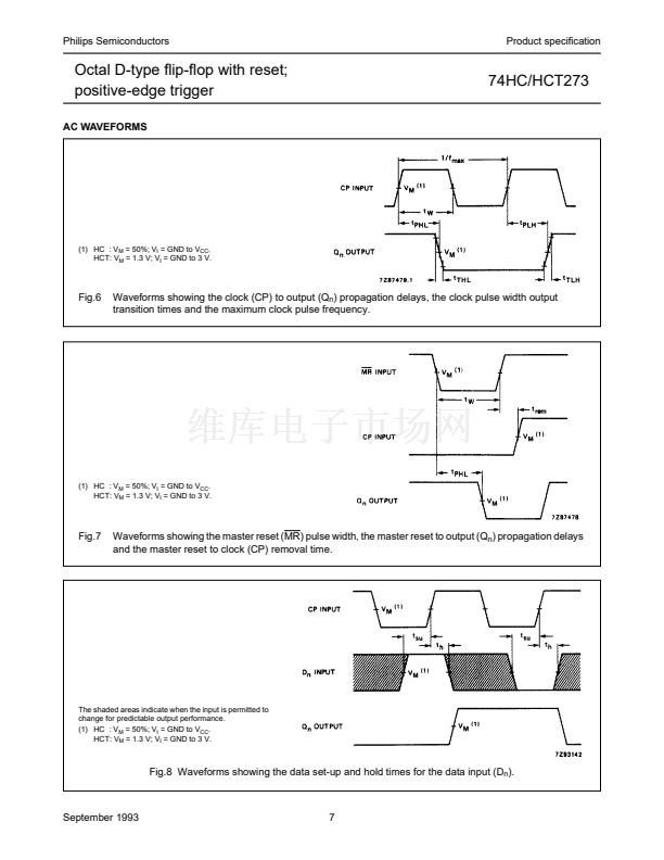
Fig.6
Fig.7
Fig.6
Fig.6
Fig.7
Fig.7
Fig.8
Fig.8
Fig.6
TEST CONDITIONS
master reset pulse width 16
LOW
removal time
MR to CP
set-up time
D
n
to CP
hold time
D
n
to CP
maximum clock pulse
frequency
10
12
3
30
September 1993
6


 1
1
 2
2
 3
3
 4
4
 5
5
 6
6
 7
7
 8
8
