PRELIMINARY DATA SHEET
SILICON TRANSISTOR
碌
PA813T
NPN SILICON EPITAXIAL TRANSISTOR
(WITH BUILT-IN 2
脳
2SC4570) SMALL MINI MOLD
碌
PA813T has built-in 2 transistors which were developed for UHF.
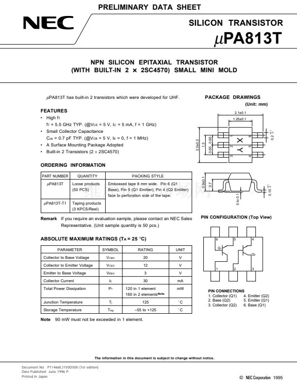
PACKAGE DRAWINGS
(Unit: mm)
2.1鹵0.1
1.25鹵0.1
FEATURES
鈥?High f
T
f
T
= 5.5 GHz TYP. (@V
CE
= 5 V, I
C
= 5 mA, f = 1 GHz)
0.65 0.65
2.0鹵0.2
C
ob
= 0.7 pF TYP. (@V
CB
= 5 V, I
E
= 0, f = 1 MHz)
鈥?A Surface Mounting Package Adopted
鈥?Built-in 2 Transistors (2
脳
2SC4570)
1.3
2
3
ORDERING INFORMATION
0.9鹵0.1
PART NUMBER
QUANTITY
Loose products
(50 PCS)
PACKING STYLE
Embossed tape 8 mm wide. Pin 6 (Q1
Base), Pin 5 (Q1 Emitter), Pin 4 (Q2 Emitter)
face to perforation side of the tape.
0.7
碌
PA813T-T1
Taping products
(3 KPCS/Reel)
Remark
If you require an evaluation sample, please contact an NEC Sales
Representative. (Unit sample quantity is 50 pcs.)
PIN CONFIGURATION (Top View)
ABSOLUTE MAXIMUM RATINGS (T
A
= 25
擄
C)
PARAMETER
Collector to Base Voltage
Collector to Emitter Voltage
Emitter to Base Voltage
Collector Current
Total Power Dissipation
SYMBOL
V
CBO
V
CEO
V
EBO
I
C
P
T
RATING
20
12
3
30
120 in 1 element
160 in 2 elements
Note
125
鈥?5 to +125
UNIT
V
V
6
Q
1
5
0 to 0.1
4
Q
2
1
2
3
V
mA
mW
Junction Temperature
Storage Temperature
T
j
T
stg
藲C
藲C
PIN CONNECTIONS
4. Emitter (Q2)
1. Collector (Q1)
5. Emitter (Q1)
2. Base (Q2)
6. Base (Q1)
3. Collector (Q2)
Note
90 mW must not be exceeded in 1 element.
The information in this document is subject to change without notice.
Document No. P11466EJ1V0DS00 (1st edition)
Date Published June 1996 P
Printed in Japan
漏
0.15
鈥?
+0.1
碌
PA813T
4
5
0.2
鈥?
1
6
+0.1
鈥?Small Collector Capacitance
XY
1995


 1
1
 2
2
 3
3
 4
4
 5
5
 6
6
 7
7
 8
8
