鈾?/div>
High temperature soldering:
250擄C/10 seconds at terminals
N
T
E
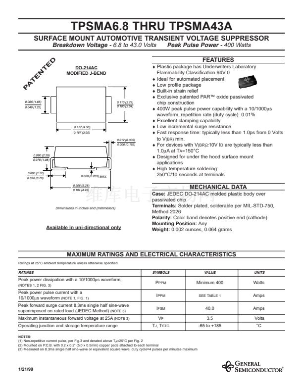
MECHANICAL DATA
Case:
JEDEC DO-214AC molded plastic body over
passivated chip
Terminals:
Solder plated, solderable per MIL-STD-750,
Method 2026
Polarity:
Color band denotes positive end (cathode)
Mounting Position:
Any
Weight:
0.002 ounces, 0.064 grams
Dimensions in inches and (millimeters)
Available in uni-directional only
MAXIMUM RATINGS AND ELECTRICAL CHARACTERISTICS
Ratings at 25擄C ambient temperature unless otherwise specified.
RATINGS
SYMBOLS
VALUE
UNITS
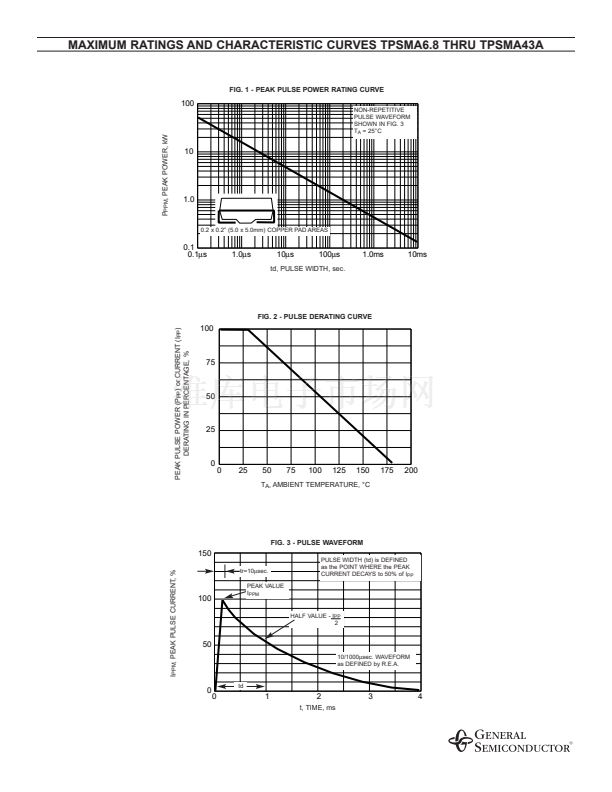
Peak power dissipation with a 10/1000碌s waveform,
(NOTES 1, 2 FIG. 3)
P
PPM
I
I
FSM
V
F
T
J
, T
STG
Minimum 400
SEE TABLE 1
Watts
Amps
Amps
Volts
擄C
Peak power pulse current with a
10/1000碌s waveform
(NOTE 1, FIG. 1)
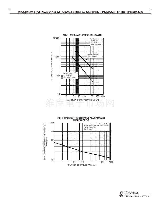
Peak forward surge current 8.3ms single half sine-wave
superimposed on rated load (JEDEC Method)
(NOTE 3)
Maximum instantaneous forward voltage at 25A
(NOTE 3)
Operating junction and storage temperature range
40.0
3.5
-65 to +185
NOTES:
(1) Non-repetitive current pulse, per Fig.3 and derated above T
A
=25擄C per Fig. 2
(2) Mounted on P.C.B. with 0.2 x 0.2鈥?(5.0 x 0.5mm) copper pads attached to each terminal
(3) Measured on 8.3ms single half sine-wave or equivalent square wave, duty cycle=4 pulses per minutes maximum
1/21/99


 1
1
 2
2
 3
3
 4
4
