鈥?/div>
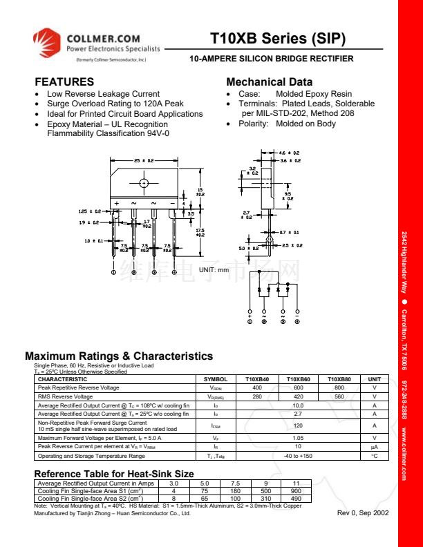
Case:
Molded Epoxy Resin
Terminals: Plated Leads, Solderable
per MIL-STD-202, Method 208
Polarity: Molded on Body
!
2542 Highlander Way
!
Carrollton, TX 75006
!
!
UNIT: mm
Maximum Ratings & Characteristics
Single Phase, 60 Hz, Resistive or Inductive Load
T
a
= 25潞C Unless Otherwise Specified
CHARACTERISTIC
Peak Repetitive Reverse Voltage
RMS Reverse Voltage
Average Rectified Output Current @ T
C
= 108潞C w/ cooling fin
Average Rectified Output Current @ T
a
= 25潞C w/o cooling fin
Non-Repetitive Peak Forward Surge Current
10 mS single half sine-wave superimposed on rated load
Maximum Forward Voltage per Element, I
F
= 5.0 A
Peak Reverse Current per element at V
R
= V
RRM
Operating and Storage Temperature Range
SYMBOL
V
RRM
V
R(RMS)
I
o
I
o
I
FSM
V
F
I
R
T
J
,T
stg
T10XB40
400
280
T10XB60
600
420
10.0
2.7
120
1.05
10
-40 to +150
T10XB80
800
560
UNIT
V
V
A
A
A
V
碌A(chǔ)
擄C
972-248-2888
www.collmer.com
Reference Table for Heat-Sink Size
Average Rectified Output Current in Amps
2
Cooling Fin Single-face Area S1 (cm )
2
Cooling Fin Single-face Area S2 (cm )
3.0
4
8
5.0
75
65
7.5
180
100
9
500
310
11
900
490
Note: Vertical Mounting at T
a
= 40潞C. HS Material: S1 = 1.5mm-Thick Aluminum, S2 = 3.0mm-Thick Copper
Manufactured by Tianjin Zhong 鈥?Huan Semiconductor Co., Ltd.
Rev 0, Sep 2002


 1
1
 2
2
