750ps max. LEN to output
700ps max. D to output
鈩?/div>
input pulldown resistors
s
Fully compatible with Motorola MC10E/100E154
s
Available in 28-pin PLCC package
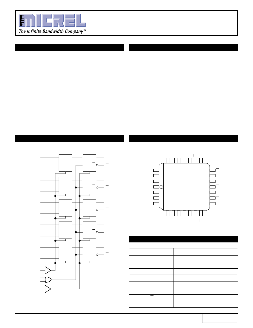
DESCRIPTION
The SY10/100E154 offer five 2:1 multiplexers followed
by latches with differential outputs, designed for use in
new, high-performance ECL systems. The two external
Latch-Enable signals (LEN
1
, LEN
2
) are gated through a
logical OR operation before use as control for the five
latches. When both LEN
1
and LEN
2
are at a logic LOW, the
latches are transparent, thus presenting the data from the
multiplexers at the output pins. If either LEN
1
or LEN
2
(or
both) are at a logic HIGH, the outputs are latched.
The multiplexer operation is controlled by the SEL(Select)
signal which selects one of the two bits of input data at each
mux to be passed through.
The MR (Master Reset) signal operates asynchronously
to make all Q outputs go to a logic LOW.
BLOCK DIAGRAM
PIN CONFIGURATION
V
CCO
Q
4
Q
4
D
4b
D
4a
D
3b
D
3a
D
0a
MUX
D
0b
D
1a
MUX
D
1b
D
2a
MUX
D
2b
D
3a
MUX
D
3b
D
4a
MUX
D
4b
SEL
LEN
1
LEN
2
MR
SEL
SEL
SEL
SEL
SEL
D
Q
Q
0
Q
0
SEL
26
27
28
1
2
3
4
E Q
NR
D
Q
25 24 23 22 21 20 19
18
17
Q
3
Q
3
V
CC
Q
2
Q
2
Q
1
Q
1
Q
1
Q
1
LEN
1
LEN
2
V
EE
MR
D
0a
E Q
NR
D
Q
PLCC
TOP VIEW
J28-1
16
15
14
13
12
Q
2
Q
2
D
0b
E Q
NR
D
Q
5
6
7
8
9
10 11
D
1a
D
1b
V
CCO
Q
0
D
2a
D
2b
Q
3
Q
3
E Q
NR
D
Q
PIN NAMES
Q
4
Q
4
Pin
D
0a
鈥揇
4a
D
0b
鈥揇
4b
SEL
LEN
1
, LEN
2
MR
Q
0
鈥換
4
Q
0
鈥換
4
V
CCO
Function
Input Data a
Input Data b
Data Select Input
Latch Enables
Master Reset
True Outputs
Inverted Outputs
V
CC
to Output
Rev.: C
Amendment: /1
E Q
N R
1
Q
0
Issue Date: February, 1998


 1
1
 2
2
 3
3
 4
4
