STR-S6401
AND
STR-S6401F
OFF-LINE SWITCHING REGULATORS
鈥?WITH POWER MOSFET OUTPUT
DRAIN
1
LATCH
OSC.
Data Sheet
28101
SOURCE
2
GATE
POWER
GROUND
SOFT
START
OVER-CURRENT
PROTECTION
V IN
3
PWM
+
4
+
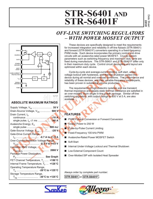
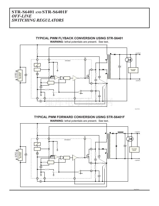
These devices are specifically designed to meet the requirements
for increased integration and reliability in off-line flyback (STR-S6401)
and forward (STR-S6401F) converters operating in a fixed-frequency
PWM mode. Each device incorporates the primary control and drive
circuits with an avalanche-rated power MOSFET. Crucial system
parameters such as switching frequency and maximum duty cycle are
fixed during manufacture. The STR-S6401 and STR-S6401F differ only
in their maximum duty cycle. Control circuit decoupling and layout are
optimized within each device.
Cycle-by-cycle and average-current limiting, soft start, under-
voltage lockout with hysteresis, and thermal shutdown protect the
device during all normal and overload conditions. The performance and
reliability of these devices, and their variable-frequency counterparts,
has been proven in substantial volume production.
The requirements of high dielectric isolation and low transient
thermal impedance and steady-state thermal resistance are satisfied in
an over-molded, 9-pin single in-line power package. Similar off-line
switching regulators, with output ratings to 800 V at 5 A, are also
available.
5
6
7
UVLO
REF.
SIGNAL
GROUND
FDBK
8
9
Dwg. PK-003
ABSOLUTE MAXIMUM RATINGS
Supply Voltage, V
IN
............................
35 V
Drain-Source Voltage, V
DS
...............
500 V
Drain Current, I
D
continuous ...................................
鹵
10 A
single pulse, t
w
鈮?
ms ..................
鹵
40 A
Avalanche Energy, E
A
single pulse ...............................
500 mJ
Gate-Source Voltage, V
GS
................
鹵
20 V
Gate-Drive Current Range,
I
G
.................................
-0.7 A to +1.5 A
Over-Current Protection Voltage Range,
V
OCP
.............................
-0.3 V to +4.0 V
Insulation RMS Voltage,
V
WM(RMS)
.....................................
2000 V
Package Power Dissipation,
P
D
........................................
See Graph
FET Channel Temperature, T
J
......
+150
擄
C
Internal Frame Temperature, T
F
...
+125
擄
C
Operating Temperature Range,
T
A
...............................
-20
擄
C to +125
擄
C
Storage Temperature Range,
T
stg
.............................
-30
擄
C to +125
擄
C
D
S
I
O
C
T
N
D
E
N
U
E
N
ER
I
FEATURES
s
Output Power to 250 W
R
P
U
Y
D
L
O
N
O
T
C
E
C
s
PWM Flyback Conversion or Forward Conversion
s
Pulse-by-Pulse Current Limiting
鈥?/div>
F
R
O
R
s
Fixed-Frequency 100 kHz PWM
s
Avalanche-Rated Power MOSFET Switch
s
Soft Start
s
Internal Under-Voltage Lockout and Thermal Shutdown
s
Low External Component Count
s
Over-Molded SIP with Isolated Heat Spreader
F
E
Always order by complete part number:
STR-S6401
or
STR-S6401F
.
鈩?/div>
next


 1
1
 2
2
 3
3
 4
4
 5
5
 6
6
 7
7
 8
8
