SPICE MODELS: S2A S2B S2D S2G S2J S2K S2M S2AA S2BA S2DA S2GA S2JA S2KA S2MA
S2A/A - S2M/A
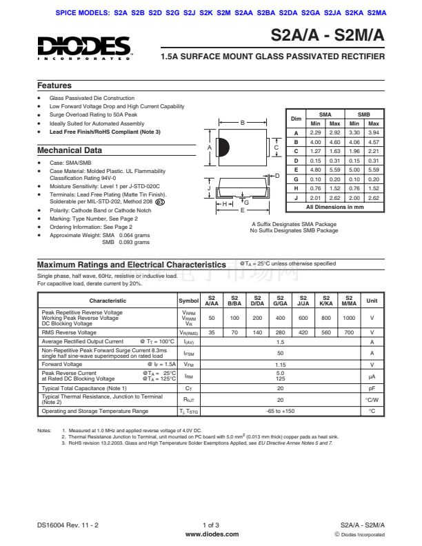
1.5A SURFACE MOUNT GLASS PASSIVATED RECTIFIER
Features
路
路
路
路
路
Glass Passivated Die Construction
Low Forward Voltage Drop and High Current Capability
Surge Overload Rating to 50A Peak
Ideally Suited for Automated Assembly
Lead Free Finish/RoHS Compliant (Note 3)
SMA
Min
2.29
4.00
1.27
0.15
4.80
0.10
0.76
2.01
Max
2.92
4.60
1.63
0.31
5.59
0.20
1.52
2.62
SMB
Min
3.30
4.06
1.96
0.15
5.00
0.10
0.76
2.00
Max
3.94
4.57
2.21
0.31
5.59
0.20
1.52
2.62
B
Dim
A
Mechanical Data
路
路
路
路
路
路
路
路
Case: SMA/SMB
Case Material: Molded Plastic. UL Flammability
Classification Rating 94V-0
Moisture Sensitivity: Level 1 per J-STD-020C
Terminals: Lead Free Plating (Matte Tin Finish).
Solderable per MIL-STD-202, Method 208
e
3
Polarity: Cathode Band or Cathode Notch
Marking: Type Number, See Page 2
Ordering Information: See Page 2
Approximate Weight: SMA 0.064 grams
SMB 0.093 grams
A
B
C
C
D
E
D
J
G
H
J
H
G
E
All Dimensions in mm
A Suffix Designates SMA Package
No Suffix Designates SMB Package
Maximum Ratings and Electrical Characteristics
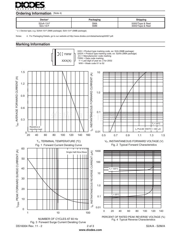
Single phase, half wave, 60Hz, resistive or inductive load.
For capacitive load, derate current by 20%.
Characteristic
Peak Repetitive Reverse Voltage
Working Peak Reverse Voltage
DC Blocking Voltage
RMS Reverse Voltage
Average Rectified Output Current
@ T
T
= 100擄C
Non-Repetitive Peak Forward Surge Current 8.3ms
single half sine-wave superimposed on rated load
Forward Voltage
Peak Reverse Current
at Rated DC Blocking Voltage
Typical Total Capacitance (Note 1)
Typical Thermal Resistance, Junction to Terminal
(Note 2)
Operating and Storage Temperature Range
@ I
F
= 1.5A
@T
A
= 25擄C
@T
A
= 125擄C
Symbol
V
RRM
V
RWM
V
R
V
R(RMS)
I
(AV)
I
FSM
V
FM
I
RM
C
T
R
qJT
T
j,
T
STG
S2
A/AA
50
35
@T
A
= 25擄C unless otherwise specified
S2
B/BA
100
70
S2
D/DA
200
140
S2
G/GA
400
280
1.5
50
1.15
5.0
125
20
20
-65 to +150
S2
J/JA
600
420
S2
K/KA
800
560
S2
M/MA
1000
700
Unit
V
V
A
A
V
碌A(chǔ)
pF
擄C/W
擄C
Notes:
1. Measured at 1.0 MHz and applied reverse voltage of 4.0V DC.
2. Thermal Resistance Junction to Terminal, unit mounted on PC board with 5.0 mm
2
(0.013 mm thick) copper pads as heat sink.
3. RoHS revision 13.2.2003. Glass and High Temperature Solder Exemptions Applied, see
EU Directive Annex Notes 5 and 7.
DS16004 Rev. 11 - 2
1 of 3
www.diodes.com
S2A/A - S2M/A
茫
Diodes Incorporated


 1
1
 2
2
 3
3
