NTE1409 & NTE1409N
Integrated Circuit
Electronic Channel Selector
Description:
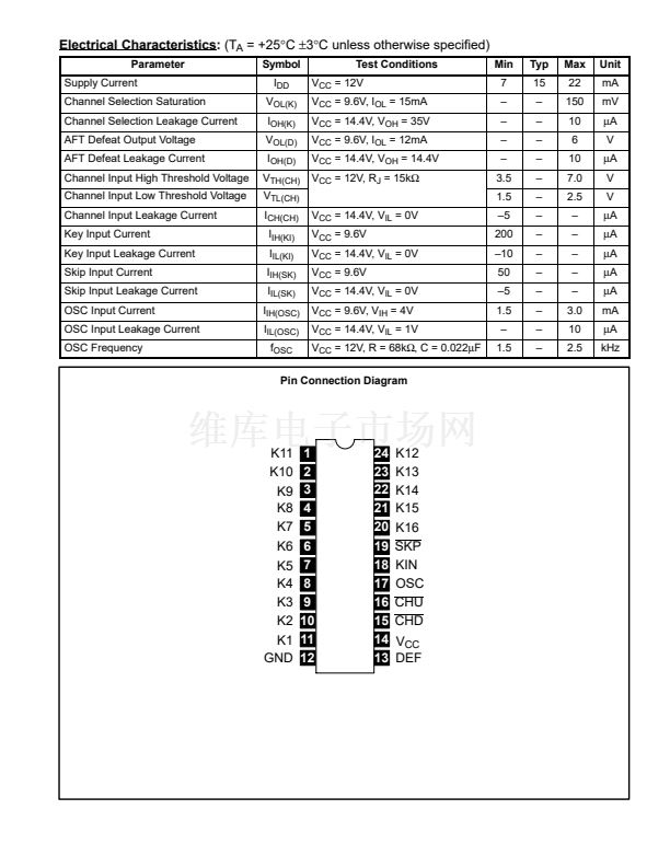
The NTE1409 is an electronic channel selector integrated circuit in a 24鈥揕ead DIP type package
capable of selecting up to 16 channels. The output terminals are design to permit direct driving of
LEDs or neon tubes.
It consists of a Clock Oscillator circuit, a Channel Up and Down circuit, a Channel skip circuit, a 4 bit
Up and Down Counter circuit, a 1鈥?6 Decoder circuit and a 16 channel Output Buffer circuit.
Features:
D
LED Direct Drive
D
Low Power Consumption
D
Up to 16 Channel Selections
D
Internal Schmitt Trigger Circuit
D
Power ON Initial Channel Set
D
TV, Radio, etc. Channel Selection Use.
D
Can be Used with NTE1758 Direct Address Remote Control System
Absolute Maximum Ratings:
(T
A
= +25擄C unless otherwise specified)
Supply Voltage, V
CC
. . . . . . . . . . . . . . . . . . . . . . . . . . . . . . . . . . . . . . . . . . . . . . . . . . . . . . . . . . . . . . . . 15V
Input Current to Channel Selection Circuit, I
K1鈥?1
, I
K20鈥?4
. . . . . . . . . . . . . . . . . . . . . . 鈥?mA to 50mA
Input Current to Control Circuit, I
C15鈥?9
. . . . . . . . . . . . . . . . . . . . . . . . . . . . . . . . . . . . . . 鈥?mA to 10mA
Input Current to Control Circuit, I
C13
. . . . . . . . . . . . . . . . . . . . . . . . . . . . . . . . . . . . . . . . 鈥?mA to 20mA
Output Voltage to Channel Selection Circuit (V
CC
= 12V), V
K1鈥?1
, V
K20鈥?4
. . . . . . . . . 鈥?.5V to 50V
Output Voltage to Control Circuit (V
CC
= 12V), V
13
. . . . . . . . . . . . . . . . . . . . . . . . . . . . 鈥?.5V to 14.4V
Input Voltage to Control Circuit (V
CC
= 12V), V
17
. . . . . . . . . . . . . . . . . . . . . . . . . . . . . . . 鈥?.5V to V
CC
Power Dissipation, P
D
. . . . . . . . . . . . . . . . . . . . . . . . . . . . . . . . . . . . . . . . . . . . . . . . . . . . . . . . . . 350mW
Operating Temperature Range, T
opt
. . . . . . . . . . . . . . . . . . . . . . . . . . . . . . . . . . . . . . . . . . 鈥?0擄 to +75擄C
Storage Temperature Range, T
stg
. . . . . . . . . . . . . . . . . . . . . . . . . . . . . . . . . . . . . . . . . . 鈥?0擄 to +125擄C
Recommended Operating Conditions:
(T
A
= +25擄C unless otherwise specified)
Parameter
Supply Voltage
Channel Selection Input Current
Clock Oscillation Frequency
Symbol
V
CC
I
K
f
OSC
Test Conditions
Min
9.6
鈥?/div>
鈥?/div>
Typ
12.0
15
2
Max
14.4
next


 1
1
 2
2
 3
3
