MM54HC192 MM74HC192 Synchronous Decade Up Down Counters
MM54HC193 MM74HC193 Synchronous Binary Up Down Counters
January 1988
MM54HC192 MM74HC192
Synchronous Decade Up Down Counters
MM54HC193 MM74HC193
Synchronous Binary Up Down Counters
General Description
These high speed synchronous counters utilize advanced
silicon-gate CMOS technology to achieve the high noise im-
munity and low power consumption of CMOS technology
along with the speeds of low power Schottky TTL The
MM54HC192 MM74HC192 is a decade counter and the
MM54HC193 MM74HC193 is a binary counter Both coun-
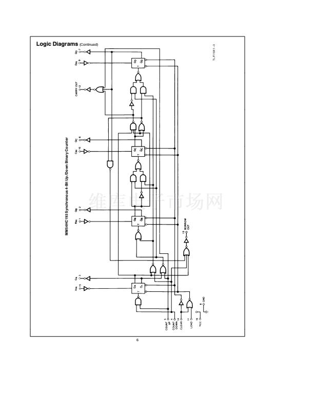
ters have two separate clock inputs an UP COUNT input
and a DOWN COUNT input All outputs of the flip-flops are
simultaneously triggered on the low to high transition of ei-
ther clock while the other input is held high The direction of
counting is determined by which input is clocked
These counters may be preset by entering the desired data
on the DATA A DATA B DATA C and DATA D inputs
When the LOAD input is taken low the data is loaded inde-
pendently of either clock input This feature allows the count-
ers to be used as divide-by-n counters by modifying the
count length with the preset inputs
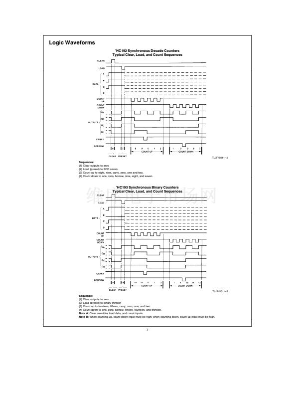
In addition both counters can also be cleared This is ac-
complished by inputting a high on the CLEAR input All 4
internal stages are set to a low level independently of either
COUNT input
Both a BORROW and CARRY output are provided to en-
able cascading of both up and down counting functions The
BORROW output produces a negative going pulse when the
counter underflows and the CARRY outputs a pulse when
the counter overflows The counters can be cascaded by
connecting the CARRY and BORROW outputs of one de-
vice to the COUNT UP and COUNT DOWN inputs respec-
tively of the next device
All inputs are protected from damage due to static dis-
charge by diodes to V
CC
and ground
Features
Y
Y
Y
Y
Y
Y
Typical propagation delay
Count up to Q 28 ns
Typical operating frequency 27 MHz
Wide power supply range 2 鈥?6V
Low quiescent supply current 80
mA
maximum
(74HC Series)
Low input current 1
mA
maximum
4 mA output drive
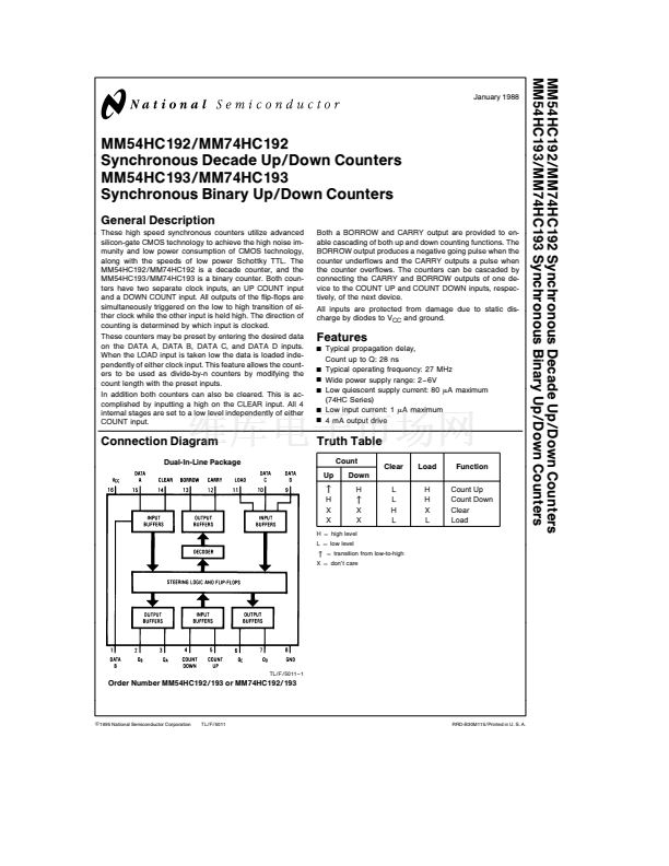
Connection Diagram
Dual-In-Line Package
Truth Table
Count
Up
Down
H
Clear
L
L
H
L
Load
H
H
X
L
Function
Count Up
Count Down
Clear
Load
u
H
X
X
L
e
low level
u
X
X
H
e
high level
u
e
transition from low-to-high
X
e
don鈥檛 care
TL F 5011 鈥?1
Order Number MM54HC192 193 or MM74HC192 193
C
1995 National Semiconductor Corporation
TL F 5011
RRD-B30M115 Printed in U S A


 1
1
 2
2
 3
3
 4
4
 5
5
 6
6
 7
7
 8
8
