KSC2518
KSC2518
High Speed, High Voltage Switching
鈥?Low Collector Saturation Voltage
鈥?Specified of Reverse Biased SOA With Inductive Load
1
TO-220
2.Collector
3.Emitter
NPN Epitaxial Silicon Transistor
Absolute Maximum Ratings
T
C
=25擄C unless otherwise noted
Symbol
V
CBO
V
CEO
V
EBO
I
C
I
CP
I
B
P
C
T
J
T
STG
Collector-Base Voltage
Collector-Emitter Voltage
Emitter-Base Voltage
Collector Current (DC)
*Collector Current (Pulse)
Base Current (DC)
Collector Dissipation (T
C
=25擄C)
Junction Temperature
Storage Temperature
Parameter
1.Base
Value
500
400
7
4
8
1
40
150
- 55 ~ 150
Units
V
V
V
A
A
A
W
擄C
擄C
* PW鈮?50碌s, Duty Cycle鈮?0%
Electrical Characteristics
T
C
=25擄C unless otherwise noted
Symbol
V
CEO
(sus)
V
CEX
(sus)1
V
CEX
(sus)2
I
CBO
I
CER
I
CEX1
I
CEX2
I
EBO
h
FE1
h
FE2
V
CE
(sat)
V
BE
(sat)
t
ON
t
STG
t
F
Parameter
Collector-Emitter Sustaining Voltage
Collector-Emitter Sustaining Voltage
Collector-Emitter Sustaining Voltage
Collector Cut-off Current
Collector Cut-off Current
Collector Cut-off Current
Test Condition
I
C
= 2A, I
B1
= 0.4A, L = 1mH
I
C
= 2A, I
B1
= -I
B2
= 0.4A
T
a
= 125擄C, L = 180碌H, Clamped
I
C
= 4A, I
B1
= 0.8A, -I
B2
= 0.4A
T
a
= 125擄C, L = 180碌H, Clamped
V
CB
= 400V, I
E
= 0
V
CE
= 400V, R
BE
= 51鈩?@ T
C
= 125擄C
V
CE
= 400V, V
BE
(off) = -1.5V
V
CE
= 400V, V
BE
(off) = -1.5V @
T
C
= 125擄C
V
EB
= 5V, I
C
= 0
V
CE
= 5V, I
C
= 0.3A
V
CE
= 5V, I
C
= 1.5A
I
C
= 1.5A, I
B
= 0.3A
I
C
= 1.5A, I
B
= 0.3A
V
CC
= 150V, I
C
= 2A
I
B1
= - I
B2
= 0.4A
R
L
= 75鈩?/div>
20
10
Min.
400
450
400
10
1
10
1
10
80
1
1.5
1
2.5
0.7
V
V
碌s
碌s
碌s
Max.
Units
V
V
V
碌A(chǔ)
mA
碌A(chǔ)
mA
碌A(chǔ)
Emitter Cut-off Current
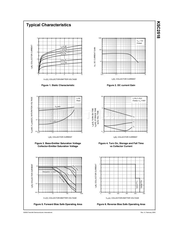
* DC Current Gain
* Collector-Emitter Saturation Voltage
* Base-Emitter Saturation Voltage
Turn ON Time
Storage Time
Fall Time
* Pulse Test: PW鈮?50碌s, Duty Cycle鈮?% Pulsed
h
FE
Classification
Classification
h
FE1
漏2000 Fairchild Semiconductor International
R
20 ~ 40
O
30 ~ 60
Y
40 ~ 80
Rev. A, February 2000


 1
1
 2
2
 3
3
 4
4
 5
5
