e1467D
32-kHz Clock CMOS IC with Digital Trimming and Alarm
Features
D
32-kHz voltage regulated oscillator
D
1.1 V to 2.2 V operating-voltage range
D
Integrated capacitors for digital trimming
D
Suitable for up to 12.5 pF quartz
D
Trimming inputs insensitive to stray capacitance
D
Output pulse formers
D
Mask options for motor period and pulse width
D
Low resistance output for bipolar stepping motor
D
Alarm function
D
Motor-fast-test function
Pad Configuration
SC4 SC3 SC2 SC1
*
VDD
VSS
General Description
9
OSCIN
*
OSCOUT
1
13
12
11 10
2
8
e 1467D
7
6
ALOUT
MOT2
MOT1R
9611897
**ALIN /
MTEST
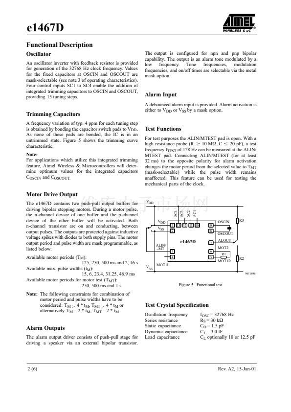
The e1467D is an integrated circuit in CMOS Silicon
Gate Technology for analog clocks. It consists of a
32-kHz oscillator, frequency divider, output pulse
formers, push-pull motor drivers and alarm output.
Integrated capacitors are mask-selectable to accomodate
the external quartz crystal. Additional capacitance can be
selected through pad bonding for trimming the oscillator
frequency.
**MOT1L
*) The pads for V
DD
and OSCOUT are interchangeable
per mask option
**) The pads for ALIN/-MTEST and MOT1L are inter-
changeable per mask-option
Figure 4. Pad configuration
Absolute Maximum Ratings
Parameters
Supply voltage
Input voltage range, all inputs
Output short circuit duration
Power dissipation (DIL package)
Operating ambient temperature range
Storage temperature range
Lead temperature during soldering at 2 mm
distance, 10 seconds
Symbol
V
SS
V
IN
P
tot
T
amb
T
stg
T
sld
Value
鈥?.3 to 5 V
(V
SS
鈥?0.3 V)
x
V
IN
x
(V
DD
+ 0.3 V)
indefinite
125 mW
鈥?0 to +70
鈥?0 to + 125
260
Unit
V
V
mW
擄C
擄C
擄C
Absolute maximum ratings define parameter limits
which, if exceeded, may permanently change or damage
the device.
All inputs and
Microcontrollers鈥?/div>
outputs in Atmel Wireless &
circuits are protected against
Rev. A2, 15-Jan-01
脧
脧脧
脧
脧脧
脧
脧脧
脧
脧脧
脧
脧
脧脧
脧 脧脧脧脧脧脧脧
脧脧
脧 脧脧脧脧脧脧脧
脧脧
3
4
5
electrostatic discharges. However, precautions to
minimize the build-up of electro-static charges during
handling are recommended.
This circuit is protected against supply voltage reversal
for typically 5 minutes.
1 (6)


 1
1
 2
2
 3
3
 4
4
 5
5
 6
6
