鈥?/div>
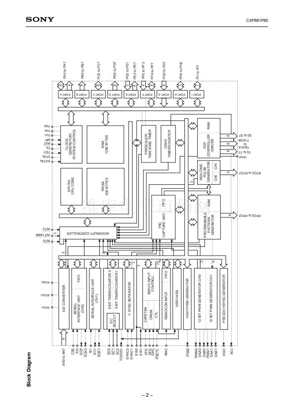
Peripheral function
鈥?A/D converter
8 bits, 8 channels, successive approximation system
(Conversion time of 20碌s/16MHz)
鈥?Serial interface
Incorporated 8-bit 8-stage FIFO for data
(Auto transfer for 1 to 8 bytes), 1 channel
8-bit clock sync type, 1 channel
鈥?Timer
8-bit timer/counter, 2 channel
19-bit time base timer
32kHz timer/counter
鈥?High precision timing pattern generator
PPG 8 pins, 21-stage programmable circuit
RTG 5 pins, 2 channels
鈥?PWM/DA gate output
12 bits, 2 channels (Repetitive frequency 62.5kHz/16MHz)
DA gate pulse output, 13 bits, 4 channels
鈥?Servo input control
Capstan FG, Drum FG/PG, CTL input
鈥?VSYNC separator
鈥?FRC capture unit
Incorporated 26-bit and 8-stage FIFO
鈥?PWM output
14 bits, 1 channel
鈥?VISS/VASS circuit
Pulse duty auto detection circuit
鈥?Remote control reception circuit
8-bit pulse measurement counter, 6-stage FIFO
鈥?Fluorescent display panel controller/driver Maximum 144-segment display possible
Hardware key scan function (Maximum 16 x 3 key matrix available)
Dimmer function
High voltage drive output (40V)
Incorporated pull-down resistor (mask option)
鈥?Tri-state output
PPG 1 pin, RTG 1 pin, output 8 pins
鈥?Pseudo HSYNC output function
鈥?High speed head switching circuit
鈥?/div>
Interruption
22 factors, 15 vectors, multi-interruption possible
鈥?/div>
Standby mode
SLEEP/STOP
鈥?/div>
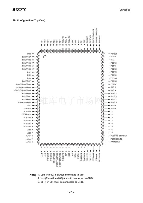
Package
100-pin plastic QFP
Sony reserves the right to change products and specifications without prior notice. This information does not convey any license by
any implication or otherwise under any patents or other right. Application circuits shown, if any, are typical examples illustrating the
operation of the devices. Sony cannot assume responsibility for any problems arising out of the use of these circuits.
next


 1
1
 2
2
 3
3
 4
4
 5
5
 6
6
 7
7
 8
8
 9
9
 10
10
 11
11
 12
12
 13
13
 14
14
 15
15
 16
16
 17
17
 18
18
 19
19
 20
20
 21
21
 22
22
 23
23
 24
24
 25
25
