driver. When the current limiter is activated, the 鏗俛g output
changes state conditionally. If the control input is the 鈥?鈥?state,
the 鏗俛g output will remain in a 鈥?鈥?state. If the control input is in
reference level of 335mV, the 鏗俛g output will remain in the 鈥?鈥?/div>
state. If the control input is the 鈥?鈥?state and the sense input is
equal to or greater than the 335mV reference level, the 鏗俛g
output goes to the 鈥?鈥?state. The output 鏗俛g switch may be used
to accurately establish dwell timing in automotive applications.
When the control input goes to 鈥?鈥? the 鏗俛g is reset to 鈥?鈥? Noise-
immunity hold-off is used to prevent pre-triggering of the 鏗俛g
output and is noted as t
D
in the timing diagram of Figure 2.
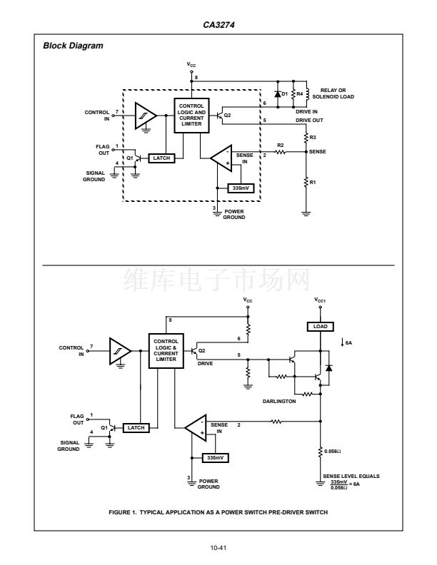
The 鏗俛g output may be used for diagnostic feedback via the
current sense input to detect a fault mode. In this case the
sampled drive current is either from the emitter of the CA3274
internal power transistor or an external output ampli鏗乪r, such as
a darlington power transistor or power-FET output stage. The
CA3274 has separate power and signal grounds to minimize
transient-loop feedback to the input ground and thus prevent
false triggering of the output. Optionally, the output from the
CA3274 may be taken from the open collector (DRIVE IN) at
pin 6. An external resistor at pin 6 may be used to set the level
at which Q2 will saturate, providing additional limiting protection
for the maximum forward-drive from the CA3274.
Features
鈥?Drive-Current Limiting at Output
鈥?Current-Sense Buffer and Reference
鈥?200mA Driver Current Capability
鈥?Logic-Level Control Input
鈥?Current Limiting Flag Output
鈥?50dB Minimum PSRR
鈥?5碌s Typical Switch Time
鈥?Separate Signal and Power Grounds
Applications
鈥?Solenoid Switch Driver
鈥?Relay Driver
鈥?Lamp Control Switch
鈥?Ignition Coil Pre-Driver
鈥?Constant Current Driver
鈥?Current Limiting Switch
鈥?Fault Output Sense Appliance
鈥?Power Supply Fault Mode Control
Ordering Information
PART NUMBER
CA3274E
TEMPERATURE
RANGE
-40
o
C to +85
o
C
PACKAGE
8 Lead Plastic DIP
Pinout
CA3274 (PDIP)
TOP VIEW
FLAG OUT
SENSE IN
POWER GND
SIGNAL GND
1
2
3
4
8
7
6
5
V
CC
SUPPLY
CONTROL IN
DRIVE IN
DRIVE OUT
CAUTION: These devices are sensitive to electrostatic discharge; follow proper IC Handling Procedures.
http://www.intersil.com or 407-727-9207
|
Copyright
漏
Intersil Corporation 1999
File Number
2222.2
10-40


 1
1
 2
2
 3
3
 4
4
 5
5
