鈥?/div>
Sensitive Gate Trigger Current 鈥?200
碌A(chǔ)
Maximum
Low Reverse and Forward Blocking Current 鈥?100
碌A(chǔ)
Maximum, TC = 125擄C
Low Holding Current 鈥?5 mA Maximum
Glass-Passivated Surface for Reliability and Uniformity
BRY55-30*
thru 600*
SCRs
0.8 AMPERE RMS
30 TO 600 VOLTS
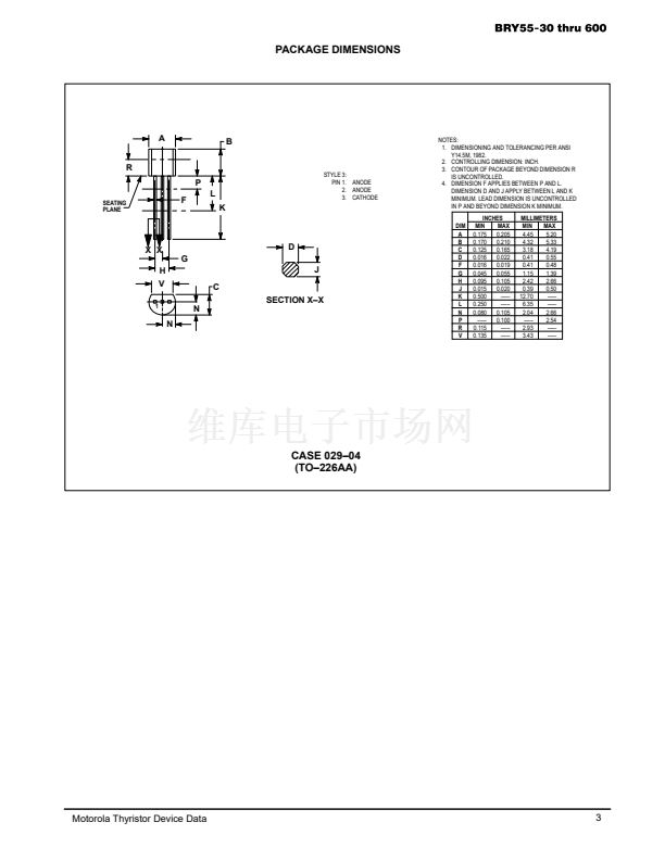
CASE 29-04
(TO-226AA)
STYLE 3
MAXIMUM RATINGS
(TJ = 25擄C unless otherwise noted.)
Rating
Peak Repetitive Forward and Reverse Blocking Voltage(1)
(RGK = 1000
鈩?
TJ = 25 to 125擄C)
Marking: BRY55-1 . . . BRY55-30
-2 . . . BRY55-60
-3 . . . BRY55-100
-4 . . . BRY55-200
-6 . . . BRY55-400
-7 . . . BRY55-500
-8 . . . BRY55-600
Forward Current RMS (All Conduction Angles)
Peak Forward Surge Current, TA = 25擄C
(1/2 Cycle, Sine Wave, 60 Hz)
Circuit Fusing Considerations, TA = 25擄C
(t = 8.3 ms)
Peak Gate Power 鈥?Forward, TA = 25擄C
Peak Gate Current Forward, TA = 25擄C
(300
碌s,
120 PPS)
Peak Gate Voltage 鈥?Reverse
Operating Junction Temperature Range @ Rated VRRM and VDRM
Storage Temperature Range
Symbol
VRRM, VDRM
30
60
100
200
400
500
600
IT(RMS)
ITSM
I2t
PGM
IGFM
VGRM
TJ
Tstg
0.8
8
0.15
0.1
1
5
鈥?0 to +125
鈥?0 to +150
+230
Amp
Amps
A2s
Watt
Amp
Volts
擄C
擄C
擄C
Value
Unit
Volts
Lead Solder Temperature ( 1.5 mm from case, 10 s max.)
*European part numbers only. Package is Case 29 with Leadform 18.
t
1. VDRM and VRRM for all types can be applied on a continuous basis. Ratings apply for zero or negative gate voltage; however, positive gate
voltage shall not be applied concurrent with negative potential on the anode. Blocking voltages shall not be tested with a constant current
source such that the voltage ratings of the devices are exceeded.
Motorola Thyristor Device Data
漏
Motorola, Inc. 1995
1


 1
1
 2
2
 3
3
 4
4
