鈥?/div>
Battery Packs
Cellular & Cordless Telephones
PDAs, Camcorders, and Cell Phones
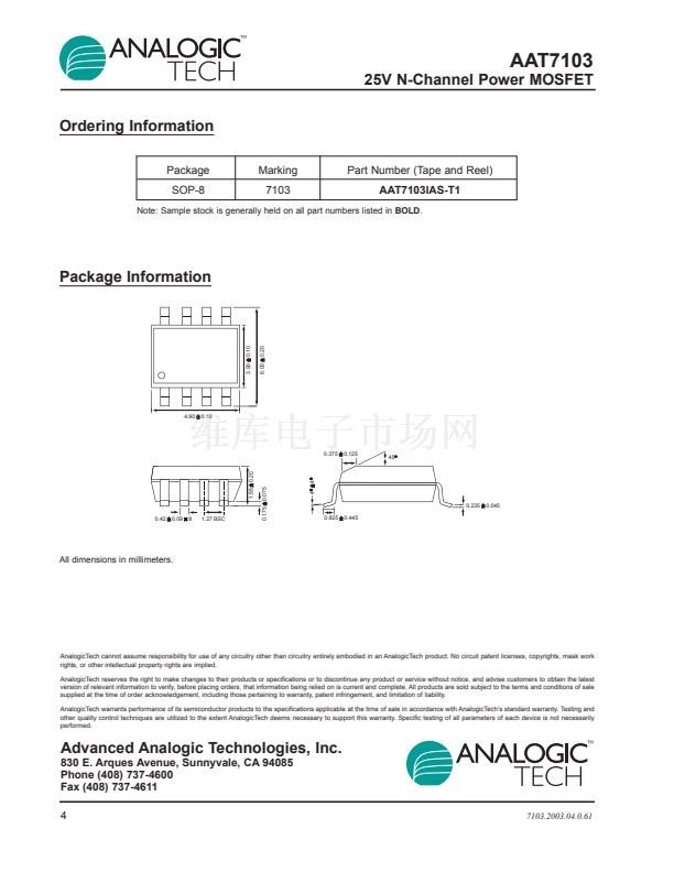
Dual SOP-8 Package
Preliminary Information
Top View
D1
8
D1
7
D2
6
D2
5
1
S1
2
G1
3
S2
4
G2
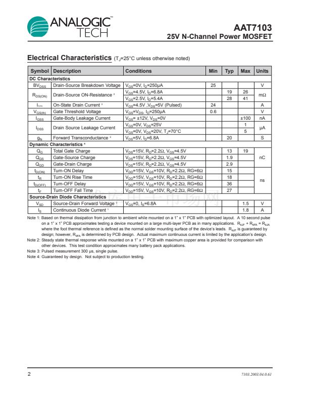
Absolute Maximum Ratings
Symbol
V
DS
V
GS
I
D
I
DM
I
S
P
D
T
J
, T
STG
(T
A
=25擄C unless otherwise noted)
Value
25
鹵12
鹵6.8
鹵5.4
鹵24
1.8
2.0
1.25
-55 to 150
Description
Drain-Source Voltage
Gate-Source Voltage
Continuous Drain Current @ T
J
=150擄C
1
Units
V
T
A
= 25擄C
T
A
= 70擄C
Pulsed Drain Current
3
Continuous Source Current (Source-Drain Diode)
1
T
A
= 25擄C
Maximum Power Dissipation
1
T
A
= 70擄C
Operating Junction and Storage Temperature Range
A
W
擄C
Thermal Characteristics
Symbol
R
胃JA
R
胃JA2
R
胃JF
Description
Typical Junction-to-Ambient steady state, one FET on
Maximum Junction-to-Ambient Figure, t < 10 sec.
1
Typical Junction-to-Foot, one FET on
1
2
Value
100
62.5
35
Units
擄C/W
擄C/W
擄C/W
7103.2003.04.0.61
1


 1
1
 2
2
 3
3
 4
4
