74F114 Dual JK Negative Edge-Triggered Flip-Flop
April 1988
Revised August 1999
74F114
Dual JK Negative Edge-Triggered Flip-Flop
with Common Clocks and Clears
General Description
The 74F114 contains two high-speed JK flip-flops with
common Clock and Clear inputs. Synchronous state
changes are initiated by the falling edge of the clock. Trig-
gering occurs at a voltage level of the clock and is not
directly related to the transition time. The J and K inputs
can change when the clock is in either state without affect-
ing the flip-flop, provided that they are in the desired state
during the recommended setup and hold times relative to
the falling edge of the clock. A LOW signal on S
D
or C
D
prevents clocking and forces Q or Q HIGH, respectively.
Simultaneous LOW signals on S
D
and C
D
force both Q and
Q HIGH.
Asynchronous Inputs:
LOW input to S
D
sets Q to HIGH level
LOW input to C
D
sets Q to LOW level
Clear and Set are independent of Clock
Simultaneous LOW on C
D
and S
D
makes both Q and Q HIGH
Ordering Code:
Order Number
74F114SC
74F114PC
Package Number
M14A
N14A
Package Description
14-Lead Small Outline Integrated Circuit (SOIC), JEDEC MS-120, 0.150 Narrow
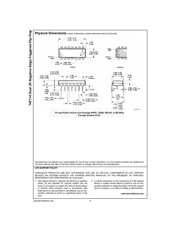
14-Lead Plastic Dual-In-Line Package (PDIP), JEDEC MS-001, 0.300 Wide
Devices also available in Tape and Reel. Specify by appending the suffix letter 鈥淴鈥?to the ordering code.
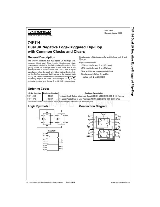
Logic Symbols
Connection Diagram
IEEE/IEC
漏 1999 Fairchild Semiconductor Corporation
DS009474
www.fairchildsemi.com


 1
1
 2
2
 3
3
 4
4
 5
5
 6
6
