鈰?/div>
high-gain amplification and oscillation at 3 GHz or over
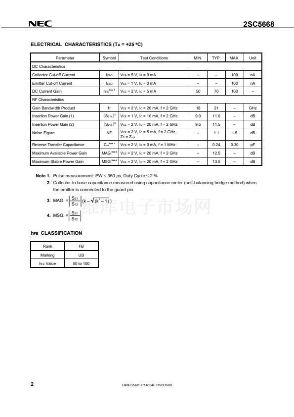
NF = 1.1 dB TYP., G
a
= 11 dB @ f = 2 GHz, V
CE
= 2 V, I
C
= 5 mA
鈥?Maximum available power gain: MAG. = 12.5 dB TYP. @ f = 2 GHz, V
CE
= 2 V, I
C
= 20 mA
鈥?High f
T
: f
T
= 21 GHz TYP. @ f = 2 GHz, V
CE
= 2 V, I
C
= 20 mA
鈥?f
T
= 25 GHz 鈥淯HS0鈥?(Ultra High Speed Process) technology adopted
鈥?Flat-lead 3-pin thin-type ultra super minimold (t = 0.59 mm)
ORDERING INFORMATION
Part Number
2SC5668
2SC5668-T1
Quantity
50 pcs (Non reel)
3 kpcs/reel
Supplying Form
鈥?8 mm wide embossed taping
鈥?Pin 3 (collector) face the perforation side of the tape
Remark
To order evaluation samples, consult your NEC sales representative (Unit sample quantity is 50 pcs).
ABSOLUTE MAXIMUM RATINGS (T
A
= +25
擄
C)
Parameter
Collector to Base Voltage
Collector to Emitter Voltage
Emitter to Base Voltage
Collector Current
Total Power Dissipation
Junction Temperature
Storage Temperature
Symbol
V
CBO
V
CEO
V
EBO
I
C
P
tot
Note
Ratings
15
3.3
1.5
35
115
150
鈭?5
to +150
Unit
V
V
V
mA
mW
擄C
擄C
T
j
T
stg
2
Note
Mounted on 1.08 cm
脳
1.0 mm (t) glass epoxy substrate
Because this product uses high-frequency technology, avoid excessive static electricity, etc.
The information in this document is subject to change without notice. Before using this document, please
confirm that this is the latest version.
Not all devices/types available in every country. Please check with local NEC representative for
availability and additional information.
Document No. P14854EJ1V0DS00 (1st edition)
Date Published June 2000 NS CP(K)
Printed in Japan
漏
2000


 1
1
 2
2
 3
3
 4
4
 5
5
 6
6
 7
7
 8
8
 9
9
 10
10
 11
11
 12
12
 13
13
 14
14
 15
15
 16
16
 17
17
 18
18
 19
19
 20
20
